Oct 16, 2026
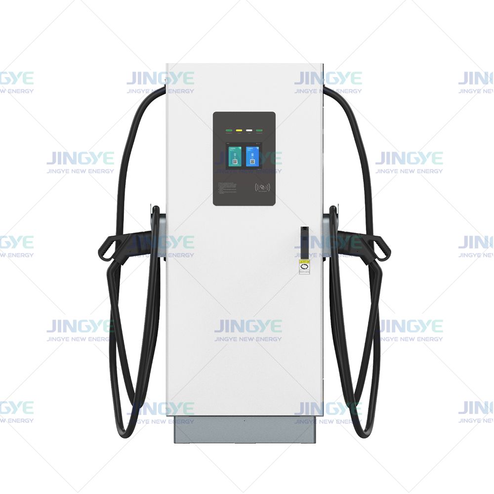
Transformer sizing for commercial EV charging stations is a key task for every DC Fast EV Charger Manufacturer and site owner. DC fast charging, peak demand, and electrical capacity directly affect the cost and safety of a project. An undersized transformer can cause voltage drops, overheating, nuisance trips, and slow charging. An oversized unit increases equipment, installation, and standby costs. The correct design must match the charger rating, vehicle demand, operating schedule, and utility service.
Many project teams begin with the total charger nameplate power, but this number does not always equal the site's real demand. Power factor, charging diversity, load profile, and future expansion also affect the transformer kVA rating. A commercial EV charging station may need a larger transformer than a simple total kW calculation suggests. The following guide explains how to make a practical transformer load calculation for DC fast chargers.
To size a transformer for a commercial EV charging station, add the expected simultaneous charger load, auxiliary loads, and planned expansion. Then divide the result by the expected power factor and apply the required design margin. For example, ten 150 kW DC fast chargers operating at 90 percent coincidence, with a 0.95 power factor and 50 kW of auxiliary load, require about 1,474 kVA before expansion. A 2,000 kVA transformer may be a practical selection after checking utility rules, voltage drop, harmonics, ambient temperature, protection, and local electrical codes.
Every charger has a rated output. Common commercial DC fast charger ratings include 60 kW, 120 kW, 150 kW, 180 kW, 240 kW, and 360 kW. The charger output is delivered to the vehicle. The input power from the transformer is higher because of conversion losses.
For an initial estimate, use this formula:
Input demand in kW = charger output in kW divided by charger efficiency
If a 150 kW charger operates at 95 percent efficiency, its approximate input demand is:
150 kW / 0.95 = 157.9 kW
The final design should use the manufacturer's maximum input current and maximum input power. These values may be higher than the normal operating average.
Not every charging port will operate at full power at the same time. A site with ten 150 kW chargers has a nameplate output of 1,500 kW. However, the actual peak may be lower if vehicles arrive at different times or if the energy management system limits the load.
Use a demand factor or coincidence factor based on measured data, operating plans, or a conservative engineering estimate. Do not use a low factor only to reduce the transformer price. The demand factor should reflect the busiest expected period.
| Input item | Example value | Reason for use |
|---|---|---|
| Number of chargers | 10 | Defines the total equipment count |
| Rated charger output | 150 kW each | Defines the maximum DC charging power |
| Coincidence factor | 90 percent | Estimates the simultaneous operating load |
| Charger efficiency | 95 percent | Accounts for conversion losses |
| Power factor | 0.95 | Converts real power into apparent power |
| Auxiliary load | 50 kW | Includes lighting, cooling, controls, and site equipment |
Transformers are normally rated in kVA or MVA, while chargers are often rated in kW. The basic conversion is:
Required transformer kVA = total operating kW divided by power factor
A more complete formula is:
Required kVA = [(number of chargers x charger kW x coincidence factor) / charger efficiency + auxiliary kW] / power factor
Consider a commercial site with ten 150 kW DC fast chargers. Assume a 90 percent coincidence factor, 95 percent charger efficiency, 0.95 power factor, and 50 kW of auxiliary load.
In this example, a 1,500 kVA transformer is close to the calculated operating demand. It may not provide enough capacity for temperature derating, future chargers, or long periods of full load. A 2,000 kVA transformer may provide a more practical design margin, subject to the utility's available service and the engineer's load study.
Reserve capacity supports future growth and short-term demand changes. It should not be treated as a substitute for a proper load study. A transformer that operates near its full rating for many hours can run hotter and age faster. The final selection should consider the transformer temperature rise, ambient temperature, installation method, ventilation, and expected charging schedule.
The utility usually supplies medium voltage for a large commercial EV charging station. Common primary voltages include 12.47 kV, 13.2 kV, 13.8 kV, and 24.9 kV, but the available voltage depends on the local utility.
The secondary voltage must match the charger input. Common commercial systems use 400 V, 415 V, 480 V, or 600 V three-phase power. Confirm the charger input range before ordering the transformer.
| Transformer feature | Typical commercial choice | Design question |
|---|---|---|
| Phase | Three phase | Does the charger require balanced three-phase input? |
| Frequency | 50 Hz or 60 Hz | Does it match the utility and charger rating? |
| Secondary voltage | 400 V to 600 V | Does it match the charger input voltage? |
| Transformer type | Pad mounted or dry type | Is the site indoor, outdoor, public, or space limited? |
| Cooling method | Natural air or liquid immersed | Can the transformer remove heat at peak load? |
A pad mounted transformer is often used for outdoor charging sites. It can support medium voltage service and reduce the length of large low-voltage conductors. The enclosure should provide suitable protection against weather, unauthorized access, and accidental contact.
A dry type transformer may be preferred inside a building or in a location where liquid containment is difficult. It requires adequate airflow and separation from combustible materials. The final choice depends on local code, fire protection, noise limits, environmental conditions, and utility requirements.
For a three-phase transformer, use this formula:
Current in amperes = transformer kVA x 1,000 divided by 1.732 x secondary voltage
For a 2,000 kVA transformer at 480 V:
2,000 x 1,000 / (1.732 x 480) = about 2,406 amperes
This current may require multiple parallel conductors, busway, or a custom switchboard. The design must also consider short-circuit current, overcurrent protection, cable length, conductor temperature, and installation method.
Long cable runs can reduce the voltage at the charger. Excessive voltage drop can cause charger faults or reduce available charging power. The engineer should calculate voltage drop at normal load and peak load.
For a high-power site, place the transformer close to the charger distribution equipment when possible. A medium-voltage service with a nearby transformer can reduce the length of large low-voltage conductors. This approach may lower installation losses and improve voltage stability.
Modern DC chargers use power electronics. Their input power factor is often controlled, but the result depends on the charger design and operating condition. Use the manufacturer's tested input power factor instead of assuming a value of 1.0.
Harmonic current can increase transformer heating and affect other electrical equipment. Request the charger's total harmonic distortion data. A project may need a harmonic study, line reactors, active filters, or a transformer designed for non-linear loads.
Useful design checks include:
Transformer impedance affects voltage regulation and available fault current. A lower impedance can improve voltage regulation but may increase fault current. A higher impedance can limit fault current but may produce more voltage drop under load. The selected value must work with the switchgear, protection settings, charger requirements, and utility limits.
A commercial EV charging station may add chargers as vehicle demand grows. The transformer sizing for ten EV chargers should include the planned number of chargers, not only the number installed on day one.
For example, a site may install six 180 kW chargers but reserve space and electrical capacity for four more. The transformer, medium-voltage equipment, switchgear, and utility service should be reviewed together. Increasing only the transformer size may not solve a limitation in the utility feeder or site switchboard.
An energy management system can limit the total site demand. It may assign available power among several vehicles based on battery state, departure time, or service priority. This can reduce the peak load, but the control system must be reliable and tested.
Do not use software limits to justify a smaller transformer unless the limits are enforced during every operating mode. Manual override, communication loss, firmware failure, and emergency operation should be included in the risk review.
A qualified DC Fast EV Charger Manufacturer should provide more than the charger output rating. Request the following information:
Jingye can be included in the design review by matching charger input data with the transformer, switchgear, protection, and energy management plan. Require a written calculation package. The package should show 100 percent of connected chargers, the selected demand factor, all auxiliary loads, expansion assumptions, and the final transformer kVA.
Transformer quality should be verified before shipment. Common inspection items include the following:
| Inspection item | Purpose | Typical record |
|---|---|---|
| Winding resistance | Checks winding connections and conductor condition | Measured value for each phase and tap |
| Turns ratio test | Confirms the primary to secondary voltage ratio | Ratio deviation recorded for each phase |
| Insulation resistance | Checks insulation condition before energization | Test voltage, time, temperature, and result |
| Dielectric withstand test | Checks insulation against specified electrical stress | Applied voltage and test duration |
| No-load loss | Measures core loss when the transformer is energized | Watts at rated voltage |
| Load loss | Measures winding and conductor losses | Watts at a defined reference temperature |
| Temperature rise | Confirms thermal performance | Measured rise at rated load |
The project team should identify the applicable edition of local electrical codes and product standards. Common references may include IEC 60076 for power transformers, IEEE C57.12.00 for liquid-immersed distribution transformers, UL 1561 for dry-type general-purpose transformers, UL 2202 for battery charging system equipment, and NEC Article 625 for electric vehicle charging equipment where adopted.
Standards and approval requirements vary by country and project type. The authority having jurisdiction and the utility should confirm the final requirements.
After installation, perform documented site tests. These may include insulation resistance, phase rotation, grounding continuity, protection relay settings, transformer tap position, torque verification, secondary voltage, charger communication, emergency stop operation, and a controlled load test. Record the ambient temperature and test current. A commissioning report should identify the technician, test instrument, calibration date, test value, and pass or fail result.
| Approach | How it works | Advantage | Risk |
|---|---|---|---|
| Nameplate total | Adds the rated kW of every charger | Simple and conservative | May create unnecessary cost if demand is managed |
| Demand factor | Applies a documented simultaneous-use factor | Balances capacity and cost | Can undersize the transformer if the factor is unrealistic |
| Measured load profile | Uses actual site charging data | Supports a precise design | Requires operating history or a pilot period |
| Future expansion design | Includes planned chargers and site growth | Reduces future construction work | Higher initial equipment cost |
| Managed charging design | Uses software to control the peak demand | Can reduce utility demand and transformer size | Depends on reliable controls and operating rules |
A 150 kW charger may draw more than 150 kW from the AC supply. Always include efficiency losses and the manufacturer's maximum input rating.
Cooling systems, lighting, payment systems, networking equipment, battery storage, security systems, and building loads can add significant demand. List each load in kW and identify whether it operates continuously or intermittently.
Transformer capacity can be affected by ambient temperature, enclosure design, altitude, ventilation, solar exposure, and installation spacing. Use the manufacturer's derating data instead of applying a general assumption.
The utility may limit the available fault current, service voltage, transformer ownership, meter arrangement, or maximum demand. Start the utility review early. A technically suitable transformer may still be unsuitable for the available grid connection.
The transformer, feeder breaker, charger breaker, and emergency shutdown system must operate together. Review short-circuit ratings, time-current curves, ground fault protection, surge protection, and selective coordination where required.
Transformer sizing for commercial EV charging stations requires more than adding charger nameplate ratings. The design must include simultaneous demand, charger efficiency, power factor, auxiliary loads, voltage drop, harmonics, temperature, protection, and future expansion. For a transformer size for 150 kW EV charger project or a larger commercial site, use verified charger input data and a documented load calculation.
A reliable process connects the DC Fast EV Charger Manufacturer, transformer supplier, utility, site owner, and licensed electrical engineer. With accurate data, factory inspection, site commissioning, and a clear expansion plan, the selected transformer can provide safe and stable charging performance for many years.
Oct. 20, 2026
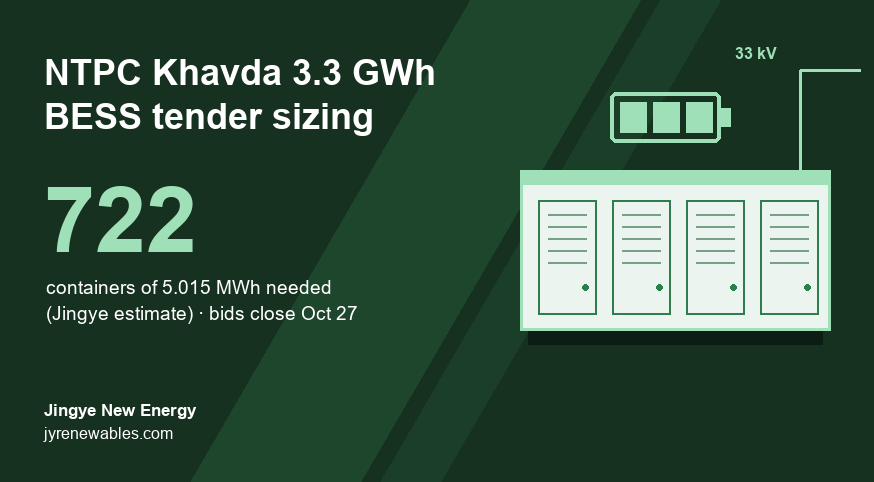
NTPC Khavda 3,300 MWh BESS Tender: How Many Containers You Really Need (2026)
NTPC Green Energy's 1,100 MW / 3,300 MWh Khavda battery tender closes on October 27, 2026. Because capacity is counted as AC energy at the grid point, we estimate it needs about 722 containers of 5.015 MWh, roughly 10% more installed battery than the headline figure.
Oct. 20, 2026
Battery Energy Storage System Architecture: Key Components Explained
A battery energy storage system architecture determines how safely and efficiently a BESS stores, controls, and delivers electricity. The main challenge for overseas buyers is choosing the right structure without creating avoidable cost, safety, or integration problems.
Oct. 19, 2026
Battery Capacity Fade in Commercial Energy Storage Systems
Battery capacity fade in commercial energy storage systems reduces the amount of energy a site can store and deliver. This battery degradation can increase demand charges, reduce backup time, and change the return on investment.
Let’s Get Started on Your New Energy Journey.