Nov 09, 2026

EV charging station cable management and connector selection affect safety, charging speed, user comfort, and site maintenance. A heavy cable can drag on the ground, while a poor cable holder can cause insulation damage and connector impact. The right charging plug, cable retraction system, and vehicle inlet design reduce these risks. As electric vehicle adoption grows, fleet operators and site owners need reliable EV charging infrastructure that works through thousands of charging cycles. This article explains how to choose an EV charger connector and build a practical EV charging cable management system. It also shows what buyers should ask a DC Fast EV Charger Manufacturer before placing an order.
The best EV charging station cable management system keeps the cable off the ground, controls bending stress, protects the connector, and allows simple user operation. Choose a connector that matches the vehicle standard, rated current, voltage, cooling method, and environmental conditions. For most DC fast charging sites, the design should include a cable holder or overhead balancer, a minimum bend radius based on the cable datasheet, IP54 or higher enclosure protection, connector temperature monitoring, and routine inspection. A qualified DC Fast EV Charger Manufacturer should also verify the system through electrical, mechanical, thermal, ingress, and communication tests before delivery.
Cable and connector requirements change according to the location and vehicle type. A passenger car site may use a 60 kW to 180 kW DC charger. A bus, truck, or logistics depot may need 240 kW to 600 kW. High-power charging creates more heat and places greater stress on the cable and connector.
Many modern DC fast chargers operate at up to 1000 V DC. Common output ratings include 125 A, 200 A, 250 A, and 400 A. A cable rated for 200 A should not be used for a system that may continuously deliver 300 A. The cable, connector, terminals, and cooling system must share the same electrical rating.
| Charging application | Typical output range | Common cable requirement | Main design concern |
|---|---|---|---|
| Passenger car DC charging | 60 kW to 180 kW | 125 A to 250 A, often air cooled | Weight, flexibility, and daily handling |
| High-power passenger car charging | 180 kW to 350 kW | 250 A to 500 A, often liquid cooled | Thermal management and connector temperature |
| Electric bus depot | 150 kW to 450 kW | 200 A to 500 A | High cycle count and cable durability |
| Electric truck charging | 350 kW to 600 kW or more | 350 A to 600 A, liquid cooled | Long cable reach and safe parking clearance |
The connector must match the vehicle inlet and the regional charging standard. Common options include CCS1, CCS2, CHAdeMO, and NACS. China also uses GB/T charging connectors. Connector choice affects communication, locking, current capacity, service parts, and vehicle compatibility.
| Connector type | Typical market use | Key characteristics | Selection question |
|---|---|---|---|
| CCS1 | North America | AC and DC charging in one vehicle inlet design | Does the target vehicle fleet use the CCS1 inlet? |
| CCS2 | Europe and many international markets | Supports three-phase AC and DC charging | Does the site require European vehicle compatibility? |
| CHAdeMO | Selected legacy and regional fleets | Dedicated DC charging connector with communication control | Will the station serve older compatible vehicles? |
| NACS | North American passenger car market | Compact connector with AC and DC charging functions | Is NACS required by the vehicle manufacturer or fleet owner? |
| GB/T DC | China | Regional connector and communication system | Does the vehicle use the GB/T charging interface? |
A suitable connector should use strong contact terminals, stable insulation, a dependable locking mechanism, and a molded strain relief. The handle should remain easy to hold when the cable is cold or wet. The connector should also resist repeated insertion, removal, drops, and side loads.
Important specifications include:
The cable should approach the vehicle inlet without twisting the connector. A side pull can stress the inlet and increase contact resistance. A support hook or overhead balancer should hold part of the cable weight. The connector should never hang from the vehicle inlet during a long charging session.
Ground contact exposes the cable to water, dirt, oil, vehicle tires, and sharp edges. It also creates a trip hazard. A wall bracket, pedestal holder, overhead boom, spring balancer, or motorized retractor can keep the cable within a controlled path.
The correct system depends on cable mass and reach. A 5 m cable may weigh several kilograms. A liquid-cooled cable with a large connector can be heavier and less flexible. The support system must carry the cable without creating a tight bend near the handle or charger outlet.
Every charging cable has a manufacturer-defined minimum bend radius. A practical design often uses a bend radius of at least 6 to 8 times the outside cable diameter, unless the cable datasheet permits a different value. For example, a cable with a 30 mm outside diameter may require a minimum bend radius of 180 mm to 240 mm.
Do not coil a high-current cable into a small loop. A tight coil can raise heat, increase mechanical stress, and reduce service life. Use a wide storage hook or guided reel that matches the cable specification.
| Management method | Best use | Advantages | Limitations |
|---|---|---|---|
| Wall or pedestal holder | Short cable reach and low traffic | Low cost and easy installation | Limited reach and less control in open areas |
| Overhead boom | Busy public charging sites | Keeps cable above the pavement | Requires structural support and clearance review |
| Spring balancer | Medium to high daily use | Reduces user lifting force | Needs adjustment for cable weight |
| Motorized retractor | Premium sites and fleet depots | Provides controlled storage and reach | Higher cost and more maintenance parts |
| Ground cable ramp | Temporary or restricted layouts | Useful where overhead support is not possible | Can limit access and requires regular inspection |
Users may pull the cable at an angle when the parking position is not ideal. The cable management system should allow enough movement without transferring the full force to the connector. Use a strain relief at the charger outlet and a flexible transition at the connector handle.
A good design also provides a clear storage position. The connector should sit in a holder with drainage. The holder should not press on the control buttons, locking latch, or communication contacts.
Air-cooled cables are common for charging currents up to about 250 A, depending on the cable design and local ambient temperature. They are simpler because they do not require coolant pipes, a pump, or a heat exchanger. Their main disadvantages are greater cable size and higher user handling force at high current.
Liquid-cooled charging cables can support higher current in a smaller cable package. A coolant circulates through the cable and connector to remove heat. These systems need a pump, coolant reservoir, flow monitoring, temperature sensors, and leak protection.
A liquid-cooled cable design should include:
Charging current should reduce when contact temperature, cable temperature, or coolant temperature reaches the control limit. The charger should stop output if the connector temperature rises beyond the safe operating value. The exact limit depends on the connector design and applicable standard.
Jingye can include thermal sensors and current derating logic in a DC fast charging project specification. Buyers should request test records that show stable operation at the rated current, the highest expected ambient temperature, and the longest planned cable length.
Standards provide a common basis for safety and interoperability. The project team should confirm the correct edition and regional requirements before production.
| Standard or specification | Area of control | Why it matters |
|---|---|---|
| IEC 61851 | Conductive charging system control and safety | Defines important charging functions and protection behavior |
| IEC 62196 | Plugs, socket outlets, vehicle connectors, and vehicle inlets | Supports connector safety and interface compatibility |
| ISO 15118 | Vehicle to charger communication | Supports advanced functions such as secure communication and managed charging |
| UL 2251 | Electric vehicle cable assemblies | Provides a North American safety framework for cable assemblies |
| IEC 60529 | Ingress protection ratings | Defines protection against dust and water entry |
| IEC 62262 | Impact protection ratings | Helps define resistance to mechanical impact |
The charger must confirm that the connector is fully inserted and locked before high-voltage output begins. The system should also stop power safely when the connector is removed or a communication fault occurs. Pilot signals, proximity detection, insulation monitoring, and emergency stop circuits should be tested as part of the complete station.
Quality begins before assembly. A manufacturer should inspect copper conductors, insulation, seals, terminals, communication wires, coolant hoses, and connector housings. Typical checks include material certificates, dimensions, surface condition, hardness, and electrical resistance.
| Inspection item | Example control point | Purpose |
|---|---|---|
| Conductor resistance | Compare with the approved cable specification | Finds incorrect conductor size or poor crimping |
| Insulation resistance | Test voltage and limit set by the applicable standard | Checks separation between live parts and protective parts |
| Withstand voltage | Apply the approved dielectric test level | Finds insulation breakdown risks |
| Contact resistance | Measure every finished connector or according to the control plan | Reduces heat caused by poor contact |
| Continuity and signal test | Check pilot, proximity, communication, and protective conductors | Confirms correct connector wiring |
| Leak and pressure test | Apply to liquid-cooled cable assemblies | Confirms coolant circuit integrity |
| Visual and dimensional check | Inspect latch, seals, strain relief, markings, and cable length | Prevents assembly and installation errors |
Commercial charging equipment may face thousands of handling actions during its service life. Testing should include connector mating cycles, cable bending, tensile loading, torsion, drop impact, vibration, and temperature cycling. Outdoor equipment should also receive water and dust ingress testing based on the target IP rating.
A practical factory acceptance plan may include:
Step 1: Define vehicle models and charging standards
Then proceed to Step 2: Set power, voltage, and current requirements
Then proceed to Step 3: Select CCS1, CCS2, CHAdeMO, NACS, or GB/T
Then proceed to Step 4: Choose cable length, bend radius, and cooling method
Then proceed to Step 5: Design the holder, balancer, boom, or retractor
Then proceed to Step 6: Confirm IP rating, impact rating, and operating temperature
Then proceed to Step 7: Review electrical, mechanical, thermal, and communication tests
Then proceed to Step 8: Complete site installation and commissioning
Then proceed to Step 9: Start scheduled inspection and maintenance
The installer should confirm that the charger stand, boom, holder, and cable path can support the total cable weight. The cable should not cross a vehicle lane unless a protected and approved system is used. The connector holder should be mounted at a comfortable height and positioned so rainwater can drain away.
Before energizing the station, check:
| Interval | Recommended action |
|---|---|
| Every day or each shift | Check connector housing, latch, cable cuts, dirt, and visible coolant leaks |
| Every month | Inspect cable holder, strain relief, retractor force, mounting bolts, and labels | Every three to six months | Check contact temperature records, connector wear, insulation condition, and communication faults |
| Every 12 months | Perform electrical safety tests, grounding checks, torque checks, and detailed cable inspection |
| After impact or overheating | Remove the connector from service until electrical and mechanical tests are complete |
A smart charging station can record connector temperature, output current, charging time, fault codes, and cooling status. A rising contact temperature at the same current may indicate terminal wear, contamination, or loose connections. Service teams can use this data to replace parts before a sudden shutdown occurs.
Jingye can support project documentation that includes wiring diagrams, inspection records, test reports, spare part lists, and commissioning procedures. For large deployments, operators should request serial number traceability for connectors, cables, power modules, and control boards.
The cable management system should reduce the force required to move the connector. A holder should allow one-handed removal without twisting the wrist. The cable should return to its storage position after use. A visible parking location also helps prevent drivers from leaving the connector on the ground.
The connector should not be used as a lever or pulled by the cable. Clear labels can show the correct grip point and storage position. The charger should not allow power delivery when the connector is not fully locked. The control system should also stop charging when abnormal temperature, insulation loss, or communication failure is detected.
A low purchase price does not always produce the lowest operating cost. A weak cable holder can increase cable replacement and service visits. A connector with poor thermal performance may require power derating and longer charging times. A well-designed system can reduce downtime and improve the user experience.
| Cost factor | Short-term effect | Long-term effect |
|---|---|---|
| Connector purchase price | Changes initial equipment cost | May affect replacement frequency |
| Cable management hardware | Adds installation cost | Reduces ground damage and user complaints |
| Liquid cooling system | Raises equipment complexity | Supports higher current and smaller cable size |
| Testing and certification | Extends pre-delivery work | Reduces field failures and compliance risk |
| Remote monitoring | Adds control and communication cost | Helps predict maintenance needs |
Select a charger platform that can support software updates, load management, and future connector options where practical. The site should also reserve space for additional power cabinets, cable supports, and switchgear. This approach is useful when daily charging sessions may increase by 20 percent or more over the first few years.
EV charging station cable management and connector design directly influence charging safety, reliability, and service cost. A strong solution matches the connector standard to the vehicle inlet, confirms current and voltage ratings, respects the cable bend radius, and keeps the cable off the ground. It also uses suitable thermal management, ingress protection, locking control, and inspection procedures. When selecting a DC Fast EV Charger Manufacturer, ask for quantified test data, traceable quality records, and clear maintenance instructions. With careful planning, Jingye and other qualified suppliers can help operators build an EV charging station that is easier to use, safer to maintain, and ready for higher charging demand.
Nov. 12, 2026
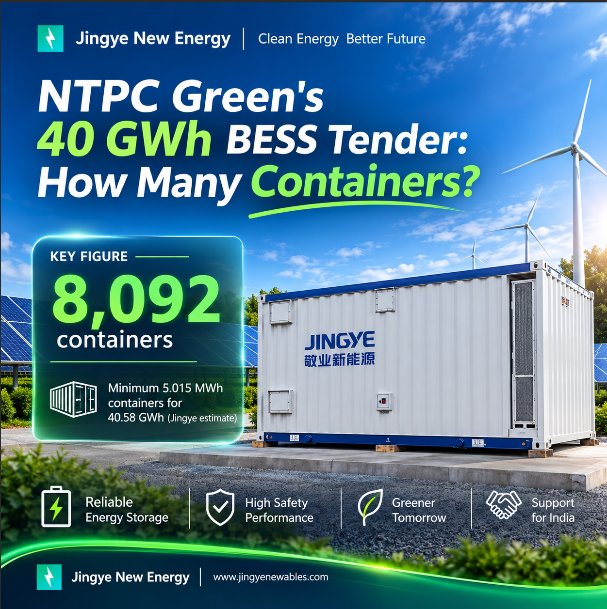
NGEL 40 GWh BESS Tender: Container Sizing, Qualification Rules and Bid Deadline (2026)
NTPC Green Energy's 10 GW / 40.58 GWh BESS tender closes on 8 December 2026 and needs at least 8,092 battery containers of 5.015 MWh. Here are the block sizes, qualification routes, turnover rules and bid steps.
Nov. 11, 2026
Brazil Tarifa Hora Certa: How Battery Storage Cuts Peak Electricity Costs from 2028
ANEEL's proposed Tarifa Hora Certa would move about 5.7 million low-voltage consumers in Brazil to time-of-use pricing from April 2028. With peak energy at R$1.73/kWh vs R$0.75 off-peak in ANEEL's Cemig example, a battery saves about R$0.90 per kWh shifted.
Nov. 10, 2026
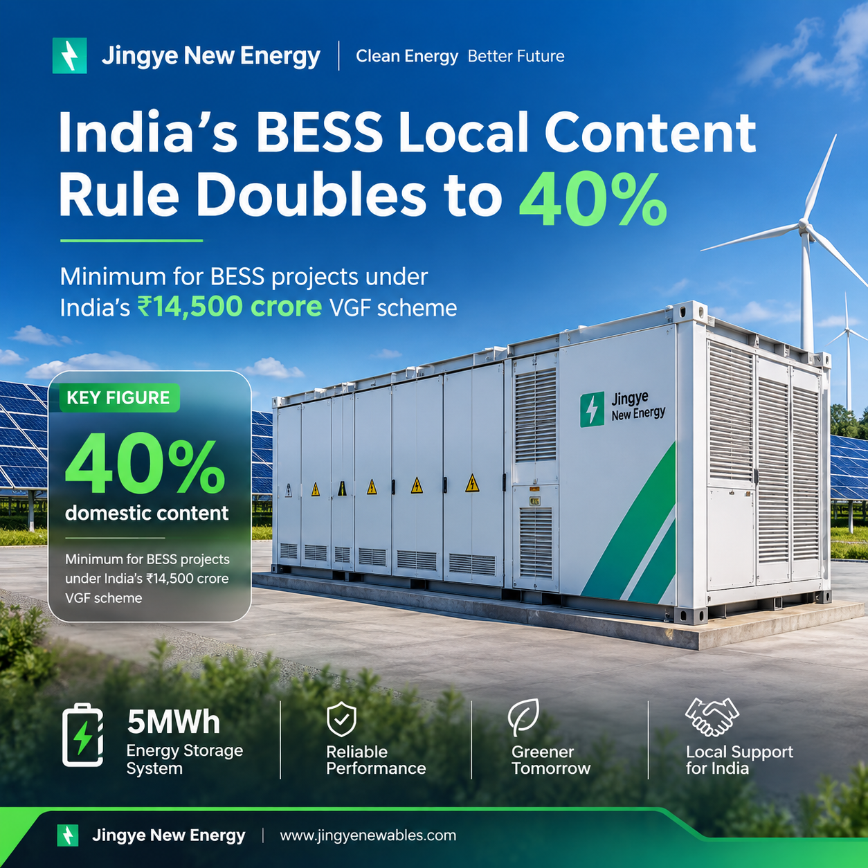
India's new ₹14,500 crore VGF scheme backs 30 GWh of battery storage, and BESS projects must now meet a 40% domestic content rule, double the earlier 20%. Here's what it means for developers, EPCs and equipment buyers.
Let’s Get Started on Your New Energy Journey.