Sep 25, 2026
Dynamic load balancing for multiple EV chargers helps a site share limited electrical power without overloading the grid connection. A commercial EV charging station may need to serve many vehicles at the same time. Smart charging can reduce peak demand and keep charging stable. Without a power management system, several chargers may draw their full rated power at once. This can trip circuit breakers, increase electricity costs, or require an expensive grid upgrade. Real-time energy monitoring helps the system see available power before it assigns power to each vehicle. The result is better use of existing charging infrastructure, shorter waiting times, and safer operation.
Many site owners ask how to balance power between EV chargers while keeping vehicles ready for use. The answer depends on the site's grid capacity, charger output, vehicle battery condition, and operating schedule. A well-designed system can also work with solar power, battery storage, and demand response programs.
Dynamic load balancing measures the total power used by a building and its EV chargers in real time. It then calculates the remaining electrical capacity and distributes that capacity among active chargers. If building demand rises, the system reduces charger output. If demand falls, it increases charger output. This method allows multiple EV chargers to operate within the site's power limit without exceeding the main connection rating.
Dynamic load balancing is an automatic control method for an EV charger power sharing system. It uses meters, communication devices, and control software to adjust charging power during each charging session.
For example, a site may have a 500 kW grid connection. The building may use 180 kW during normal operation. The charging system should not use the full remaining 320 kW because the building load can change quickly. A safety reserve may reduce the available charging power to 280 kW. The controller shares this power among all connected vehicles.
A simple control formula is:
Available charging power = Site power limit - Building demand - Safety reserve
If the site power limit is 500 kW, building demand is 180 kW, and the safety reserve is 40 kW:
500 kW - 180 kW - 40 kW = 280 kW available for EV charging
The controller can divide the 280 kW according to vehicle needs, charging priority, battery state of charge, or departure time.
A property may have enough energy for daily operations but not enough capacity for several DC fast chargers at full output. A 60 kW charger can use 60 kW when operating at its rated level. Ten such chargers could require 600 kW before the building load is included.
Electricity costs in many markets include demand charges. A short period of high power use can increase the monthly bill. Dynamic load management for fleet charging reduces unnecessary peaks by controlling charger output.
Overloaded transformers, cables, and distribution equipment can cause heat and protection trips. Load balancing keeps current within the limits set for the switchgear, cables, breakers, and site connection.
With load balancing, a site may install more charging ports without immediately increasing its grid connection. The chargers share power based on actual demand instead of reserving maximum power for every port.
Solar generation changes during the day. A controller can increase EV charging when solar output rises and reduce charging when solar output falls. This supports renewable energy integration and can lower grid energy use.
Equal sharing divides available power among active charging sessions. If 240 kW is available for four vehicles, each vehicle may receive 60 kW. This method is simple and easy to explain.
Priority charging gives more power to vehicles with urgent departure times or lower battery levels. For example, an emergency vehicle or delivery truck may receive a higher priority than a vehicle scheduled to leave later.
The system gives available power to the first vehicles that connect. This method works for simple workplace and public charging sites. It may not be the best option for a fleet with different vehicle schedules.
Time-based control charges vehicles according to a planned schedule. A fleet operator can set a target battery level and departure time. The controller then calculates the power needed to meet the target without creating a peak load.
The vehicle battery management system may reduce charging power as the battery approaches full charge. A smart charger uses this information to move available power to another vehicle. This improves total site throughput.
The control process normally follows the steps below.
An energy meter measures the power flowing through the main connection. The measurement may include the building, solar system, battery storage, and EV chargers.
The operator enters the maximum safe power level. This limit may be based on the utility contract, transformer rating, main breaker, or local electrical code.
The controller keeps a reserve to handle sudden building demand. A reserve of 5 to 15 percent is common as a design starting point, but the final value must follow the site study and equipment requirements.
The system subtracts building demand and the safety reserve from the site limit. It then checks the power needs of all connected vehicles.
The controller assigns power using a selected rule, such as equal sharing, priority, departure time, or battery state of charge.
The site controller sends updated power limits to each charger. A control cycle of about 1 second is suitable for many commercial systems. The exact cycle depends on the charger, network, and control design.
The system checks current, voltage, temperature, communication status, and total site power. If a fault occurs, it can reduce output or stop the affected charger.
The process continues while vehicles are charging. The system responds to changes in building load, solar output, battery storage, and vehicle demand.
Flow chart:
Measure site power
Then set site limit
Then subtract building demand
Then subtract safety reserve
Then calculate available EV power
Then assign power by priority or schedule
Then send charger commands
Then check equipment status
Then repeat every control cycle
| Feature | Static Load Sharing | Dynamic Load Balancing |
|---|---|---|
| Power control | Uses a fixed power limit or fixed split | Changes power according to real-time demand |
| Building load response | Usually does not respond | Responds to building demand changes |
| Use of grid capacity | May leave capacity unused | Uses available capacity more efficiently |
| Peak demand control | Limited | Strong when correctly configured |
| System complexity | Lower | Requires meters, communication, and control software |
| Best use case | Small sites with stable loads | Fleets, commercial sites, and busy public stations |
The meter measures the total import and export power at the site connection. It should support the voltage, current, frequency, and communication method used by the project.
The power distribution cabinet contains breakers, contactors, busbars, protection devices, and measurement equipment. Its current rating must match the planned charger load and future expansion.
The site controller processes meter data and sends power limits to chargers. It may run local control logic so the charging station can continue basic operation if the cloud connection is interrupted.
DC fast chargers convert AC power into controlled DC power for the vehicle battery. Common commercial ratings include 60 kW, 120 kW, 180 kW, and 240 kW. Some high-power systems support up to 350 kW, depending on the vehicle and site equipment.
Ethernet, 4G, Wi-Fi, and industrial communication protocols may connect the meter, controller, and chargers. A stable local network is important because a delayed command can reduce control accuracy.
Residual current protection, overvoltage protection, surge protection, temperature sensors, and emergency stop circuits help protect people and equipment.
| Parameter | Typical Design Question | Why It Matters |
|---|---|---|
| Site connection | Is the grid limit 250 kW, 500 kW, or higher? | Sets the total power available for the building and chargers |
| Charger output | Does each charger provide 60 kW, 120 kW, or 240 kW? | Defines charging speed and total possible demand |
| DC voltage range | Does the charger support about 200 V to 1000 V DC? | Must match different vehicle battery systems |
| Maximum current | Does the charger support 200 A, 300 A, or 500 A? | Affects cable size, thermal design, and charging speed |
| Meter update rate | Can the meter provide data every 1 second? | Supports faster load control |
| Control response | Can the system respond within 1 to 2 seconds? | Helps reduce overload risk during fast load changes |
| Protection rating | Is the outdoor equipment rated IP54 or higher? | Provides protection from dust and water exposure |
| Operating temperature | Can the equipment operate from about -20 degrees C to 50 degrees C? | Supports use in different climates |
A reliable system must support the correct charging and communication standards. IEC 61851 defines important requirements for conductive EV charging systems. ISO 15118 can support advanced vehicle-to-charger communication, including managed charging functions on compatible vehicles. OCPP 1.6 and OCPP 2.0.1 are widely used for communication between chargers and charging management software.
The final project should also follow local electrical regulations and utility requirements. Important design areas include grounding, insulation, emergency shutdown, overcurrent protection, short-circuit protection, thermal protection, and cable routing.
A DC Fast EV Charger Manufacturer should inspect more than the charging cabinet. The full load management system must be tested as one working unit.
| Inspection Stage | Example Inspection Metric | Purpose |
|---|---|---|
| Incoming material inspection | Verify model, rating, quantity, and certification documents | Prevents incorrect parts from entering production |
| Wiring inspection | Check terminal torque, cable labels, insulation, and phase sequence | Reduces wiring and heating risks |
| Meter accuracy test | Compare readings with a calibrated reference meter | Improves load control accuracy |
| Power output test | Test at low, medium, and rated output levels | Confirms stable charging performance |
| Load balancing test | Run two or more chargers at changing building loads | Confirms correct power allocation |
| Thermal test | Monitor cable, connector, busbar, and module temperatures | Finds abnormal heating |
| Protection test | Test overcurrent, overvoltage, insulation, and emergency stop functions | Confirms safe fault response |
| Communication test | Check meter, charger, controller, and cloud data exchange | Confirms system visibility and control |
| Burn-in test | Run equipment under a planned load for several hours | Identifies early component failures |
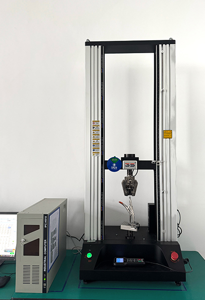
Jingye can use a staged quality process that combines component inspection, assembly checks, functional testing, communication testing, and final system verification. For a project with 20 chargers, each charger should be tested individually. The complete group should then be tested under combined load. This approach helps identify faults that may not appear during a single-charger test.
Consider a delivery fleet site with the following design:
The eight chargers cannot all operate at 120 kW at the same time. If the building demand is 180 kW, the available charging power is:
500 kW - 180 kW - 40 kW = 280 kW
The controller may allocate power as follows:
| Vehicle | Charging Priority | Assigned Power | Reason |
|---|---|---|---|
| Delivery van 1 | High | 80 kW | Departure in 45 minutes |
| Delivery van 2 | High | 70 kW | Low battery level |
| Delivery van 3 | Medium | 50 kW | Departure in 90 minutes |
| Delivery van 4 | Medium | 40 kW | Normal fleet schedule |
| Delivery van 5 | Low | 20 kW | Departure in 3 hours |
| Other vehicles | Waiting | 20 kW total | Power reserved for rotation |
Total assigned power is 280 kW. The site remains within the calculated limit. When one vehicle reaches its target battery level, the controller can move its power to another vehicle.
Office buildings often have a high daytime load. Dynamic control reduces the chance that workplace charging will increase the building's peak demand.
Shopping centers, hotels, and restaurants may see changing loads during business hours. Load balancing helps keep EV charging available while protecting the site's electrical capacity.
Fleet operators need vehicles to meet fixed routes and departure times. A schedule-based EV charging load control system can give priority to vehicles with earlier departures.
Public sites may have many vehicles arriving at random times. Dynamic load balancing can share power fairly and reduce the need to install a very large grid connection on the first day.
A site controller can combine grid power, solar generation, and battery storage. It can increase charging when solar output is high and use battery power during short demand peaks.
Confirm the available output ratings, DC voltage range, maximum current, connector types, and cable length.
Ask whether the system supports site-level control, charger-group control, equal sharing, priority charging, and scheduled charging.
Check support for OCPP, local network communication, meter integration, and cloud monitoring. Ask how the system behaves if communication fails.
Review factory test reports, insulation tests, grounding tests, output tests, thermal checks, and load balancing test results.
Make sure the controller can support future chargers. A site may start with four chargers and expand to 12 or more later.
Ask about spare parts, remote diagnostics, software updates, response times, and local technical support.
| Problem | Likely Cause | Practical Solution |
|---|---|---|
| Breakers trip when several cars connect | No site-level load control or incorrect power limit | Install a meter and set a verified site limit |
| Chargers use less power than expected | Building demand is high or the reserve is too large | Review the load profile and adjust the reserve after testing |
| Power commands arrive late | Weak network or slow communication cycle | Use a stable local network and test the control response |
| One vehicle receives too much power | Incorrect priority or sharing rule | Review the charging policy and vehicle data |
| System stops during cloud failure | No local fallback control | Use a site controller with local safety logic |
| Charging speed changes often | Building load changes or unstable renewable output | Use smoothing rules, a reserve, or battery support |
Dynamic load balancing can reduce the need for a larger transformer, larger cables, and a higher utility connection. The financial result depends on the local electricity tariff, demand charge, equipment cost, and expected charger use.
A simple cost review should compare:
For example, a site may avoid designing for 960 kW of charger output when its actual controlled load is 280 kW to 400 kW. The system does not make the chargers produce more power than their rated output. It makes better use of the power already available at the site.
Record the main breaker rating, transformer rating, utility limit, hourly building demand, solar production, and battery storage capacity.
Measure at least one typical operating period. A longer measurement period, such as 7 to 30 days, provides a better view of peak demand and daily changes.
Set goals for vehicle availability, charging time, battery target, user priority, and maximum site power.
Select equal sharing, priority charging, departure-time charging, or a combined method.
Install the meters, controller, distribution equipment, chargers, and communication network. Configure power limits and safety reserves.
Test full charger connection, sudden building load, meter failure, communication failure, emergency stop, and power recovery.
Review charging sessions, peak demand, charger utilization, alarms, and vehicle departure performance. Update the control rules when operating needs change.
Future systems will use more detailed vehicle data, energy prices, solar forecasts, and battery schedules. ISO 15118 compatible vehicles may support more advanced communication between the vehicle and charger. Fleet operators may also connect charging software with route planning and depot management systems.
Bidirectional charging may allow compatible vehicles to send power back to a building or grid. This requires additional hardware, software, utility approval, and safety controls. Dynamic load balancing will remain important because the controller must manage power in both directions.
Manufacturers such as Jingye can support these applications by combining DC charging equipment, site controllers, energy meters, protection systems, and software. A strong development plan should include laboratory testing, pilot installation, field data review, and software improvement. A project team should define measurable targets such as 1-second meter updates, 2-second control response, 95 percent successful command delivery, and complete fault event records. The final targets must be verified during site acceptance testing.
Dynamic load balancing for multiple EV chargers allows a charging site to use available power more safely and efficiently. The system measures building demand, keeps a safety reserve, and distributes the remaining capacity among active vehicles. It can reduce peak demand, delay grid upgrades, support fleet schedules, and improve the use of solar and battery storage. When selecting a DC fast EV charger manufacturer, review power ratings, communication standards, control speed, protection design, quality inspection records, and expansion options. With correct planning and testing, Jingye and other qualified manufacturers can help create a reliable EV charging station that meets present needs and supports future growth.
Sep. 28, 2026
C&I Battery Storage Capacity vs Power Rating: What Is the Difference?
Energy Storage Cabinets are increasingly used by commercial and industrial buyers to reduce peak demand, support critical loads, improve solar self-consumption, and provide backup power. However, many purchasing teams compare systems by price or cabinet size before understanding the two specifications that determine performance: battery storage capacity, measured in kilowatt-hours (kWh), and
Sep. 28, 2026
How Commercial Energy Storage Helps Reduce Demand Charges
If your electricity bill is rising because of short, high-power peaks, we can solve the problem in a simple sequence: review 12 months of interval data, identify the tariff’s demand-charge window, size Energy Storage Cabinets for the target peak, and configure an automated energy management system to discharge before the peak is billed. This step-by-step approach helps businesses reduce
Sep. 25, 2026
400V vs 800V EV Charging: Key Differences for Modern Electric Vehicles
Choosing between a 400 V and an 800 V electric vehicle is no longer only an engineering decision. It affects charging time, highway convenience, battery design, purchase price, charging site requirements, operating cost, and long-term reliability. For drivers, fleet managers, charging operators, and vehicle manufacturers comparing a DC Fast EV Charger Manufacturer, the most useful answer is not
Let’s Get Started on Your New Energy Journey.