Oct 12, 2026

Battery Storage for Solar Power Curtailment Reduction helps solar plants use electricity that would otherwise be limited or wasted. Solar curtailment occurs when a grid operator reduces photovoltaic system output because local demand, transmission capacity, or grid stability cannot accept all available power. Solar curtailment is increasing in regions with fast renewable energy growth and limited transmission expansion.
A battery Energy Storage System can capture surplus electricity during high solar production and release it later. This process improves renewable energy integration without requiring every solar plant to build new transmission lines.
The stored power can also support grid flexibility during evening demand peaks. It can provide frequency regulation, voltage support, and reserve capacity when the grid needs a fast response.
With energy arbitrage, operators charge the battery when solar power is available at a low value and discharge it when electricity demand and prices are higher. This creates a second source of project revenue.
Jingye designs and supplies energy storage equipment for commercial, industrial, and utility applications. A properly sized system can reduce lost solar production while meeting safety, performance, and service-life requirements.
Battery storage reduces solar power curtailment by charging when solar generation is higher than grid demand or export capacity. It then discharges during evening demand, grid congestion, or other periods when electricity has greater value. The battery must be sized according to the solar plant output, curtailment profile, interconnection limit, required discharge duration, and local grid rules. A solar battery storage system with a power conversion system, energy management system, thermal management, and safety controls can increase the useful output of a photovoltaic plant without changing the solar panels.
A solar plant may produce 100 MW while its grid connection allows only 70 MW of export. The remaining 30 MW must be reduced, sent to an on-site load, or stored. This condition is common when several renewable energy projects share the same transmission corridor.
Solar generation often reaches its highest level around midday. Demand may be lower at that time, especially on mild spring days or weekends. When generation exceeds demand, grid operators may curtail solar output to keep system frequency within its operating range.
Transmission lines have thermal and stability limits. A line may have enough annual capacity but still become congested for several hours. Battery storage near the solar plant can absorb power during those hours and reduce the stress on the line.
High solar output can push wholesale prices down. In some markets, prices may become negative during periods of oversupply. Charging a battery during these hours allows the operator to shift electricity sales to a later period.
Revenue meters, plant controllers, weather sensors, and power quality meters measure solar output, export power, voltage, frequency, and state of charge.
The energy management system compares solar production with the export limit and local load. The difference becomes the available charging power.
The power conversion system changes alternating current into direct current for battery charging. The battery management system controls cell voltage, current, temperature, and state of charge.
Thermal management maintains the battery within its approved operating range. Fire detection, ventilation, isolation, and emergency shutdown systems provide additional protection.
The energy management system sends stored power to the grid when solar output falls, demand increases, or the export limit becomes available.
Solar generation exceeds the export limit
Then the energy management system calculates surplus power
Then the power conversion system charges the battery
Then the battery management system checks voltage, current, and temperature
Then stored energy is dispatched during peak demand or grid congestion
Finally, the solar plant exports more useful energy and reduces curtailment
Battery sizing should use measured or modeled curtailment data. A system that is too small will leave surplus solar power unused. A system that is too large may add cost without enough additional operating revenue.
| Input | What it means | Example value |
|---|---|---|
| Solar plant rating | Maximum DC or AC generation capacity | 100 MW AC |
| Grid export limit | Maximum power allowed at the point of interconnection | 70 MW |
| Peak curtailed power | Maximum surplus that must be reduced or stored | 30 MW |
| Daily curtailment duration | Expected period of surplus generation | 3 hours |
| Battery discharge duration | Time the system must provide rated output | 2 to 4 hours |
| Round-trip efficiency | Energy returned after charging and discharging | 84% to 92% at system level |
If a solar plant has 30 MW of expected surplus for 3 hours, the theoretical surplus is:
30 MW x 3 hours = 90 MWh
If the battery system has a round-trip efficiency of 88%, approximately 79.2 MWh can be returned after the complete charge and discharge cycle. The usable battery capacity must also account for the operating state-of-charge window, reserve capacity, temperature, auxiliary loads, and capacity loss over time.
For this example, a system rated at 30 MW and 90 MWh may capture most of the curtailed energy during the selected period. A lower-capacity system, such as 20 MW and 60 MWh, may provide a better return if curtailment is less frequent or if the project has multiple revenue streams.
| Configuration | Best use | Main benefit | Important consideration |
|---|---|---|---|
| DC-coupled storage | New solar farms | Can capture DC energy before the solar inverter reaches its limit | Requires coordinated DC protection and control |
| AC-coupled storage | Existing solar plants | Can be added without replacing the solar array | Has additional conversion steps |
| Front-of-meter BESS | Utility-scale grid support | Supports export control, peak shifting, and ancillary services | Requires detailed interconnection studies |
| Behind-the-meter storage | Commercial and industrial sites | Reduces demand charges and improves on-site solar use | Operating strategy depends on the local tariff |
In an AC-coupled system, the solar inverter and battery inverter connect on the AC side. This design is suitable for an existing photovoltaic plant because the battery can be installed as an independent power block.
In a DC-coupled system, the battery connects to the solar array before the main inverter. The system can store solar energy that might otherwise be lost when the inverter reaches its AC output limit. This design may improve inverter utilization but requires careful coordination between the DC converter, battery management system, and solar controller.
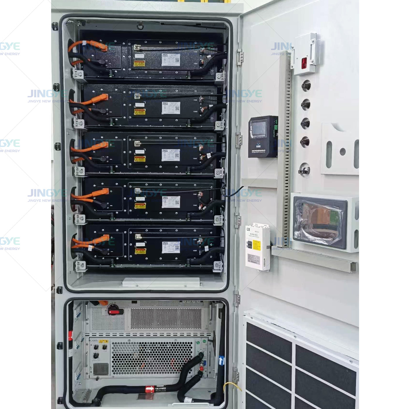
A typical containerized BESS includes battery racks, a battery management system, power conversion equipment, liquid or air cooling, fire protection, auxiliary power, and communications equipment. Common utility configurations use 10-foot, 20-foot, or 40-foot enclosures, depending on the required energy capacity and local transport limits.
Lithium iron phosphate, also called LFP, is widely used in stationary energy storage. It offers stable thermal behavior, long cycle life, and a useful balance between energy density and safety. Many LFP systems operate within a controlled cell voltage range of about 2.5 V to 3.65 V per cell, depending on the cell design and battery management strategy.
| Technical parameter | Typical design range | Why it matters |
|---|---|---|
| System voltage | 600 V to 1,500 V DC | Higher voltage can reduce current and cable losses |
| System efficiency | 84% to 92% round trip | Determines how much stored energy can be delivered |
| Response time | Milliseconds to seconds | Supports frequency response and fast power control |
| Operating temperature | Often about -20 C to 50 C with derating | Temperature affects capacity, power, and service life |
| Cycle life | Project-specific, often several thousand cycles | Influences replacement planning and total cost |
| Continuous C-rate | Commonly 0.25C to 1C | Links battery energy capacity with discharge power |
Actual values depend on the cell supplier, pack design, ambient temperature, depth of discharge, charging rate, and warranty conditions. Project documents should use tested values rather than general chemistry averages.
Battery storage for solar curtailment reduction must be tested as a complete system. Cell-level safety alone is not enough. The enclosure, cooling system, inverter, control software, fire protection, and emergency response plan must also be reviewed.
A documented factory acceptance test should include cell and module traceability, insulation resistance, hipot testing, battery capacity, voltage consistency, temperature sensor operation, communication checks, emergency shutdown, cooling performance, and inverter response.
| Inspection item | Example acceptance check |
|---|---|
| Visual and mechanical inspection | Enclosure, busbars, connectors, labels, fasteners, and seals meet approved drawings |
| Battery capacity test | Measured usable energy meets the contract value at the stated temperature and discharge rate |
| Insulation test | Resistance meets the equipment design and applicable standard |
| Power test | PCS reaches rated charge and discharge power without abnormal alarms |
| Thermal test | Cooling system maintains the approved temperature range under load |
| Control test | EMS follows dispatch commands and maintains the export limit |
| Protection test | Overvoltage, undervoltage, overcurrent, smoke, fire, and emergency-stop functions operate correctly |
Jingye project teams can use incoming inspection, process inspection, end-of-line testing, and site acceptance testing. Quality records should include serial numbers, test instruments, calibration dates, measured values, and approval signatures.
The EMS measures power at the point of interconnection. When export power approaches the permitted limit, the system increases battery charging power. When the grid has available capacity, the battery can reduce charging or discharge according to the dispatch schedule.
Solar forecasts can estimate production for the next 15 minutes, hour, or day. The EMS can reserve battery capacity before the expected solar peak. This reduces the risk that the battery is already full when curtailment begins.
The battery charges during the solar peak and discharges during the evening peak. A two-hour battery may discharge 50 MW for two hours, delivering 100 MWh before accounting for efficiency and reserve limits.
The same BESS can reduce solar curtailment, provide frequency regulation, support voltage, reduce demand charges, and participate in capacity markets. The control hierarchy must define which service has priority and how much energy must remain in reserve.
| Solution | Response speed | Typical limitation | Best application |
|---|---|---|---|
| Battery storage | Milliseconds to seconds | Capital cost and battery degradation | Short-duration shifting and fast grid services |
| New transmission | Slow to build | Permitting, land, and construction time | Long-term regional transfer capacity |
| Demand response | Minutes to hours | Depends on customer participation | Flexible commercial and industrial loads |
| Hydrogen production | Minutes to hours | Lower conversion efficiency and complex equipment | Long-duration or industrial energy use |
| Solar plant curtailment | Immediate | Lost revenue and lost renewable energy | Temporary grid balancing when no other option exists |
Battery storage is often attractive when curtailment lasts from several minutes to several hours. Transmission and other long-duration solutions may be more suitable when surplus energy continues for many days or when regional transfer capacity is the main constraint.
Step 1: Collect 12 to 36 months of solar, grid, price, and curtailment data
Step 2: Define the interconnection limit and required battery services
Step 3: Model battery power, energy capacity, efficiency, and degradation
Step 4: Select AC-coupled or DC-coupled architecture
Step 5: Complete electrical, thermal, fire, civil, and communications design
Step 6: Conduct factory inspection and performance testing
Step 7: Install, commission, and test the BESS at the project site
Step 8: Monitor curtailment reduction, battery availability, and delivered energy
Step 9: Adjust the EMS schedule based on measured operating results
Operators should track the percentage of curtailed energy captured, battery availability, round-trip efficiency, response time, state-of-charge accuracy, temperature uniformity, auxiliary energy use, and annual degradation. A clear measurement plan helps confirm whether the battery is reducing solar curtailment as expected.
The value of a battery energy storage system for solar farms usually comes from several sources. These may include avoided curtailment, energy arbitrage, capacity payments, ancillary services, demand charge reduction, and improved use of an existing grid connection.
| Value source | How storage creates value | Required data |
|---|---|---|
| Avoided curtailment | Stores solar energy that would have been limited | Historical curtailed MWh and solar value |
| Energy arbitrage | Moves energy from low-price periods to high-price periods | Hourly or sub-hourly market prices |
| Capacity value | Provides dependable power during system peaks | Capacity rules and qualifying output duration |
| Ancillary services | Responds quickly to frequency and balancing needs | Market prices and response requirements |
| Grid connection optimization | Uses one connection for solar and stored power at different times | Interconnection limit and dispatch rules |
A financial model should include battery replacement, degradation, HVAC or liquid cooling power, land preparation, insurance, service contracts, financing, and end-of-life recycling. The model should also test low, base, and high curtailment scenarios.
Battery Storage for Solar Power Curtailment Reduction allows solar plants to capture surplus generation and deliver it when the grid can accept more power. The strongest projects combine accurate curtailment data, correct battery sizing, suitable AC or DC architecture, reliable controls, and verified safety testing.
A well-designed BESS can increase renewable energy integration, improve grid flexibility, and create revenue through energy shifting and grid services. Jingye supports the development of energy storage solutions with defined technical parameters, factory quality inspections, and project-specific control strategies. For solar developers and grid operators, the right battery system turns curtailed electricity into useful and measurable energy.
Oct. 20, 2026
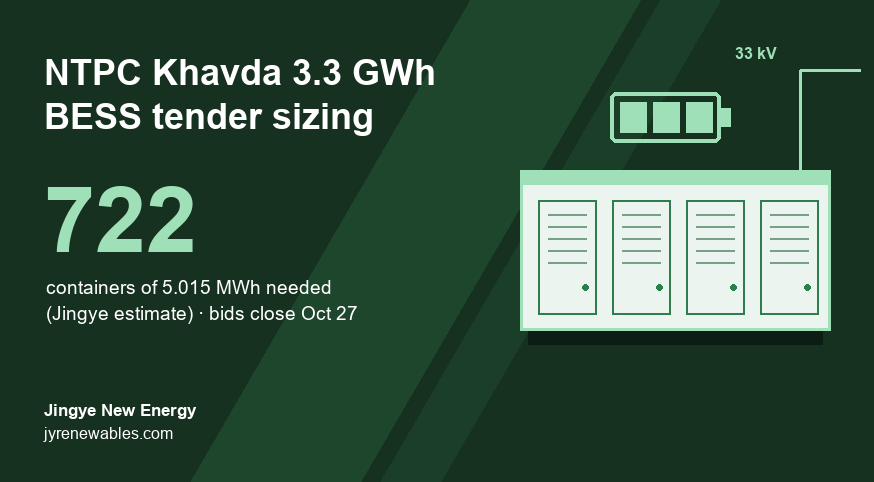
NTPC Khavda 3,300 MWh BESS Tender: How Many Containers You Really Need (2026)
NTPC Green Energy's 1,100 MW / 3,300 MWh Khavda battery tender closes on October 27, 2026. Because capacity is counted as AC energy at the grid point, we estimate it needs about 722 containers of 5.015 MWh, roughly 10% more installed battery than the headline figure.
Oct. 20, 2026
Battery Energy Storage System Architecture: Key Components Explained
A battery energy storage system architecture determines how safely and efficiently a BESS stores, controls, and delivers electricity. The main challenge for overseas buyers is choosing the right structure without creating avoidable cost, safety, or integration problems.
Oct. 19, 2026
Battery Capacity Fade in Commercial Energy Storage Systems
Battery capacity fade in commercial energy storage systems reduces the amount of energy a site can store and deliver. This battery degradation can increase demand charges, reduce backup time, and change the return on investment.
Let’s Get Started on Your New Energy Journey.