Oct 02, 2026
Connecting a battery Energy Storage System to the power grid is not only an equipment task. It requires a clear interconnection study, grid code compliance, and protection design from the first project meeting. A correct battery energy storage system grid connection plan can reduce redesign work, improve project safety, and support faster utility approval. This guide explains the main technical, commercial, and operational points for overseas buyers and distributors.

A grid-connected battery energy storage system needs a suitable point of common coupling, a power conversion system, protection and control equipment, communication functions, and approval from the local utility. The system must meet the local grid code for voltage, frequency, power quality, fault response, and safe isolation.
| Connection item | What the utility checks | Typical project evidence |
|---|---|---|
| Connection voltage | Voltage level and transformer arrangement | Single-line diagram and transformer data |
| Power rating | Import, export, and ramp limits | PCS rating and operating schedule |
| Grid behavior | Frequency, voltage, fault ride-through, and reactive power | Grid study and PCS test reports |
| Protection | Fault detection and safe disconnection | Relay settings and coordination study |
| Control and data | Remote commands, alarms, and metering | SCADA list and communication protocol |
The grid connection design depends on how the battery will operate. A system used for peak shaving may charge during low-price hours and discharge during high-demand periods. A renewable energy project may use the battery for solar shifting, output smoothing, or curtailment reduction. An ancillary service project may need rapid response and frequent changes in power.
These use cases affect the required battery capacity, inverter rating, number of daily cycles, and export limit. A 10 MW system with 20 MWh of storage has a different operating profile from a 10 MW system with 40 MWh. The first system can deliver rated power for about 2 hours, while the second can deliver it for about 4 hours under stated conditions.
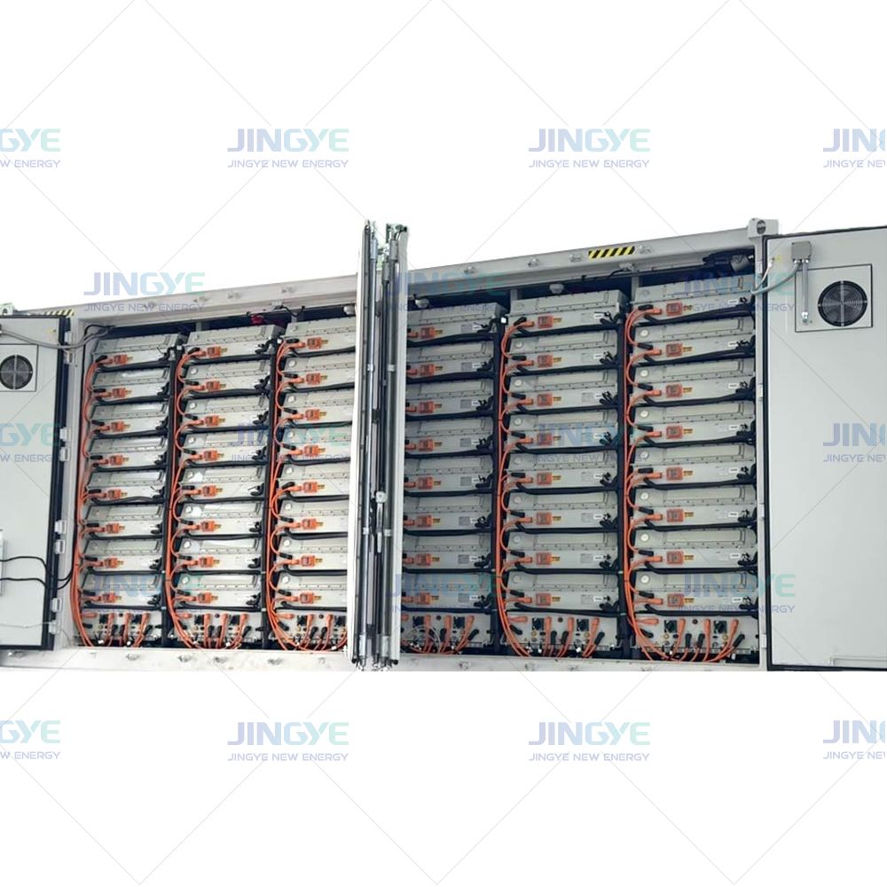
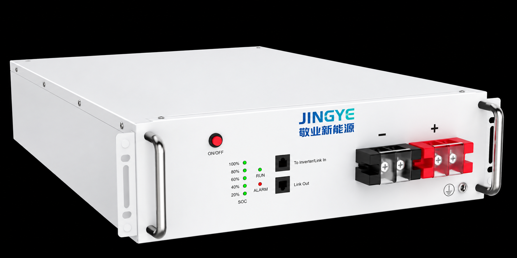
Jingye can help buyers match the battery rack, battery management system, power conversion system, and energy management system to the planned grid service. This prevents a common problem: purchasing a battery container first and discovering later that the inverter or control system cannot meet the utility requirement.
The point of common coupling, or PCC, is the electrical point where the energy storage project connects with the utility network. The PCC may be at a low-voltage bus, a medium-voltage collector system, or a high-voltage substation. Its location affects cable length, transformer size, protection settings, metering, losses, and connection cost.
A short connection route can reduce construction work, but it may not provide enough network capacity. A nearby substation may have limited fault capacity or reverse power restrictions. The utility will also check whether the project increases voltage changes, congestion, or short-circuit levels on the local network.
Do not define the PCC only by distance. A slightly longer route may offer better network strength and a simpler approval path. The final decision should follow the utility interconnection study and the commercial connection agreement.
An interconnection study shows whether the proposed BESS can operate safely without harming the grid. The study normally includes load flow, short-circuit, voltage, stability, harmonics, and protection reviews. Some markets also require electromagnetic transient analysis for inverter-based resources.
| Study type | Main question | Possible result |
|---|---|---|
| Load flow | Can the network carry the planned import and export power? | New transformer, line upgrade, or export limit |
| Short circuit | Will fault current remain within equipment ratings? | New switchgear rating or protection change |
| Voltage and reactive power | Can the system hold voltage within the required range? | Volt-var control or reactive power equipment |
| Harmonics | Will the PCS create unacceptable waveform distortion? | Filter, control adjustment, or operating limit |
| Stability | Will the plant remain controlled during grid disturbances? | Control changes or additional dynamic tests |
Provide accurate data at the study stage. The utility may request PCS models, transformer impedance, battery operating limits, control modes, fault current behavior, and plant controller settings. Incomplete data can cause repeated studies and delay the connection schedule.
Study both charging and discharging conditions. A battery is a load while charging and a generation source while discharging. The network may accept one direction of power but restrict the other. The study should also test low state of charge, high state of charge, minimum generation, maximum generation, and abnormal grid conditions.
Every country and utility has its own grid connection rules. However, most grid codes cover similar technical areas. These include frequency response, voltage control, reactive power capability, fault ride-through, active power ramp rate, anti-islanding protection, and communication with the grid operator.
The power conversion system is central to these requirements. It must convert direct current from the battery into alternating current for the grid, while controlling voltage, frequency response, active power, and reactive power. Its performance must be supported by test reports, certificates, or type approval accepted by the local authority.
Grid code compliance is not the same as using a standard inverter. The complete plant must comply. This includes the PCS, transformer, plant controller, protection relay, communication system, and operating logic.
Protection design prevents damage to people, equipment, and the utility network. It must detect faults quickly and open the correct breaker. Common functions include overcurrent, earth fault, overvoltage, undervoltage, overfrequency, underfrequency, phase loss, reverse power, and anti-islanding protection.
Protection relay coordination is especially important when the BESS is connected behind a customer transformer or near other generation assets. Incorrect settings can cause unnecessary trips, while slow settings can allow equipment damage. The final settings should be based on the short-circuit study and approved by the utility.
Grounding must cover the battery containers, transformer, switchgear, cable screens, and control equipment. The design should address touch voltage, step voltage, lightning protection, and local soil conditions. The utility may require a specific grounding resistance or testing method.
A reliable grid-connected energy storage system is a coordinated group of subsystems. The battery management system monitors cell voltage, temperature, current, insulation, and state of charge. The PCS controls electrical power. The energy management system controls schedules, dispatch, and operating limits. The plant controller communicates with the utility and coordinates the complete site.
| Subsystem | Main responsibility | Grid connection question |
|---|---|---|
| Battery management system | Cell and rack safety | Can it limit power when temperature or state of charge is outside the safe range? |
| Power conversion system | DC to AC conversion and grid control | Can it meet voltage, frequency, reactive power, and fault response rules? |
| Energy management system | Dispatch and energy scheduling | Can it follow market, utility, and site operating commands? |
| Plant controller | Overall site response | Can it keep the PCC output within the agreed limits? |
| SCADA and metering | Data and remote operation | Can the operator receive accurate real-time values and alarms? |
Check the control hierarchy before delivery. For example, a utility may send an export limit to the plant controller, which then sends a power command to several PCS units. The battery management system may reduce that command because of temperature or state of charge. This priority logic must be tested before commissioning.
Utilities need accurate information about power flow, voltage, frequency, energy, alarms, and equipment status. Revenue meters may be installed at the PCC, while internal meters measure each feeder, transformer, or PCS group. Meter accuracy classes, time synchronization, testing, and data storage periods may be specified by the grid operator.
Communication requirements can include fiber, cellular backup, remote terminal units, supervisory control and data acquisition, and approved communication protocols. The project should define who can send commands, which commands are allowed, and what happens if communication is lost.
Cybersecurity should be designed before the system is connected. Use controlled user access, separate networks for critical equipment, secure remote maintenance, event logs, software update procedures, and backup communication where required. These controls reduce the risk of unauthorized operation.
Grid approval does not replace battery safety approval. The site needs a suitable layout, emergency access, ventilation, fire detection, thermal runaway response, and safe separation between containers and other equipment. Local fire authorities may require additional water, gas detection, fire walls, emergency plans, or testing.
Site conditions also affect grid reliability. Check the ambient temperature range, humidity, altitude, flooding risk, dust, salt exposure, wind, snow load, and seismic requirements. Cooling equipment must maintain battery temperature within the supplier's operating range during charging and discharging.
A clear emergency plan should explain how to isolate the AC side, stop the PCS, disconnect the battery, contact the utility, and manage a thermal event. Operators should receive practical training before commercial operation begins.
The following process helps buyers and distributors organize technical documents and approval activities. The exact order may change by country, but the five stages are common across many projects.
Use a document register to track every revision. The register should show the responsible person, submission date, utility comments, approval status, and final revision. This simple practice can prevent old PCS settings or outdated single-line diagrams from being used during commissioning.
| Feature | AC-coupled BESS | DC-coupled BESS |
|---|---|---|
| Connection structure | Battery PCS connects on the AC side | Battery shares a DC system with solar or another source |
| Retrofit suitability | Usually suitable for existing solar plants | More suitable for new integrated designs |
| Control design | Separate generation and battery controls | More coordinated DC and AC controls |
| Grid study | Often simpler to model | May require more detailed shared inverter modeling |
| Energy efficiency | May have extra conversion steps | Can reduce some conversion losses in selected applications |
The best choice depends on the solar plant design, export limit, battery operating schedule, and utility rules. Do not select AC or DC coupling only because of initial equipment price. Compare total installed cost, control complexity, future expansion, available connection capacity, and expected annual energy throughput.
Change control is essential. If the PCS rating, transformer impedance, battery rack count, cable route, or control software changes, review the effect on the interconnection study. A small design change can affect fault current, voltage rise, protection coordination, or export capability.
Before placing an order, ask the manufacturer for a complete technical package. The package should match the country, utility, voltage level, and project operating profile. It should not be a general brochure that omits grid performance data.
Jingye supports project teams by aligning system configuration, control functions, and technical documents before shipment. Early coordination is valuable for distributors because it reduces misunderstandings between the manufacturer, EPC contractor, consultant, and local utility.
No. The system must meet the local utility's technical rules and approval process. Battery capacity alone does not prove grid suitability. The PCS, plant controller, protection system, metering, communications, and safety design must also be accepted.
The required documents vary, but the single-line diagram, equipment data, grid study, protection settings, control description, and test reports are usually central. All documents must use consistent ratings and operating limits.
The PCS directly controls the battery's exchange of power with the grid. It manages active power, reactive power, voltage response, frequency response, and fault behavior. Its tested performance strongly affects grid code compliance.
The schedule depends on the utility, voltage level, network capacity, study workload, permits, construction, and witness testing. Early submission of accurate data can reduce avoidable review cycles, but the utility controls the formal approval timeline.
Complete electrical inspection, insulation and grounding tests, relay injection tests, PCS tests, battery safety checks, communication tests, performance tests, and utility witness tests. Then submit the final as-built documents and close all approval actions.
Battery energy storage system grid connection is a complete engineering and approval process, not simply the installation of battery containers. The most important actions are to define the use case, select the PCC, complete accurate grid studies, meet grid code requirements, coordinate protection, test control systems, and prepare safety documents early.
A five-stage roadmap gives project teams a practical structure from concept to commercial operation. With correct data and early coordination, overseas buyers and distributors can reduce technical risk and make system delivery more predictable. Jingye can support this work with integrated battery storage equipment and project-focused technical cooperation.
Oct. 09, 2026
India's 50 GWh BESS Plan (GEC-III): What It Means for Battery Storage Buyers in 2026
India's Green Energy Corridor Phase III sets aside ₹50,000 crore for 50 GWh of battery storage by FY2032-33, about ₹10,000 per kWh. Here's what that budget, rising tender tariffs and the 20% local-content rule mean for developers choosing a BESS supplier.
Oct. 09, 2026
EV Charger Load Management for Commercial Charging Stations
Commercial charging sites often face high electricity bills, limited grid capacity, and slow charging during busy periods. Dynamic load balancing helps distribute available power between several chargers without exceeding the site's electrical limit. This guide explains EV charger load management in clear steps for fleet operators, property owners, and overseas EV charging distributors. Smart
Oct. 09, 2026
Battery Storage for Commercial Buildings: Key Applications
Commercial buildings face high electricity bills, power interruptions, solar energy waste, and limited grid capacity. Commercial battery storage supports peak shaving, demand charge management, and load shifting in one energy system. The best battery storage project matches the building's load profile, tariff rules, safety needs, and backup power goals.
Let’s Get Started on Your New Energy Journey.