
A battery Energy Storage System architecture determines how safely and efficiently a BESS stores, controls, and delivers electricity. The main challenge for overseas buyers is choosing the right structure without creating avoidable cost, safety, or integration problems.
A complete design includes the battery management system, power conversion system, and energy management system. These three control layers work together to measure battery conditions, convert electricity, and follow operating instructions.
The architecture must also match the project size, battery chemistry, grid rules, load profile, and installation environment. A small commercial system and a utility-scale system cannot use the same design without changes.
Thermal management, fire protection, and grid connection equipment are equally important because they protect the battery and support stable operation. These systems can also affect permits, insurance, maintenance, and total ownership cost.
This guide explains the key BESS components, their functions, common architectures, and the energy storage process in simple terms. It is written for distributors, EPC contractors, project developers, and industrial buyers.
Jingye supplies energy storage solutions designed around safe battery integration, clear system control, and practical project requirements. The best architecture is not the one with the most equipment; it is the one that delivers the required power, energy, safety, and service life at a reasonable cost.

1. What Is Battery Energy Storage System Architecture?
Battery energy storage system architecture is the organized design of hardware, software, protection devices, and communication links in a BESS. It shows how electricity moves from the grid or renewable source to the battery, and then from the battery to the load or grid.
A BESS normally has a DC battery side and an AC power side. The battery stores direct current, while most buildings, factories, and utility grids use alternating current. The power conversion system connects these two electrical worlds.
Basic energy path
The energy path is usually: renewable source or grid, switchgear, power conversion system, battery rack, battery modules, and battery cells. During discharge, the direction is reversed. Control signals move through the battery management system and energy management system.
Solar panels or grid
|
v
AC switchgear or DC combiner
|
v
Power conversion system
|
v
Battery racks and battery management system
|
v
Cells store or release energy
|
v
Energy management system controls the complete operation
2. What Are the 8 Key BESS Components?
1. Battery cells and battery modules
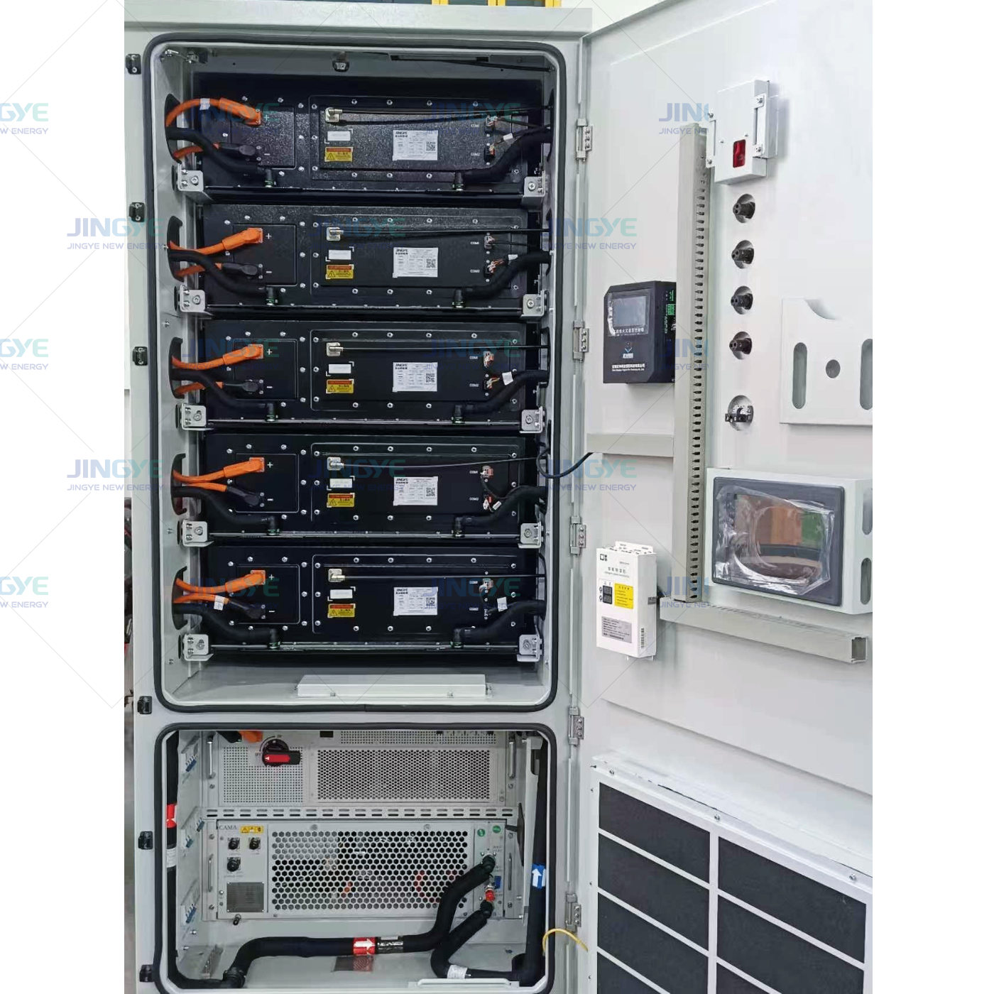
Battery cells are the basic units that store electrical energy through an electrochemical reaction. Cells are connected in series and parallel to form modules. Modules are then assembled into racks or cabinets to reach the required voltage, capacity, and output current.
Lithium iron phosphate, often called LFP, is widely used in stationary storage because it offers strong thermal stability and a long cycle life. The final choice should also consider operating temperature, expected cycles, available space, local regulations, and warranty conditions.
2. Battery management system
The battery management system, or BMS, monitors cell voltage, current, temperature, state of charge, and state of health. It balances cells and can disconnect the battery when conditions become unsafe.
A reliable BMS has several levels. The cell monitoring unit measures individual cells. The rack or module controller collects local data. The main BMS communicates with the power conversion system and energy management system.
Buyer check: Confirm the BMS measurement accuracy, balancing method, alarm levels, emergency shutdown logic, communication protocol, data records, and remote service functions.
3. Power conversion system
The power conversion system, or PCS, converts DC power from the battery into AC power for a building or grid. It converts AC power back to DC during charging. It also controls active power, reactive power, voltage, frequency, and charging limits.
PCS selection should be based on rated power, overload ability, conversion efficiency, operating voltage, grid code, protection functions, and installation conditions. A 1 MW PCS can deliver power quickly, but the battery capacity determines how long that power can continue.
4. Energy management system
The energy management system, or EMS, is the operating brain of the BESS. It uses data from the BMS, PCS, meters, weather systems, renewable generators, and building controls.
An EMS can schedule charging when electricity prices are low and discharge when prices are high. It can also perform peak shaving, solar self-consumption, backup power, demand response, frequency regulation, and state of charge control.
The EMS should not replace the safety functions of the BMS. The BMS protects the battery locally, while the EMS optimizes the complete system according to business and grid objectives.
5. Thermal management system
Battery temperature affects power output, charging speed, safety, and service life. Thermal management keeps cells within their approved temperature range and reduces temperature differences between modules.
Air cooling may suit smaller systems and mild climates. Liquid cooling can provide more uniform temperature control for high-power systems, large battery containers, and hot environments. The design should include sensors, fans or pumps, coolant controls, filters, and fault alarms.
6. Fire detection and suppression system
Fire protection is a complete safety layer, not only a fire extinguisher. It may include smoke detection, heat detection, gas detection, ventilation, alarm control, emergency stop devices, and a suitable suppression system.
The enclosure should limit unauthorized access and help control an abnormal event. The project design must follow the fire, electrical, and building requirements of the installation country. Buyers should request test reports and a clear emergency response plan.
7. Electrical balance of system
Electrical balance of system equipment connects and protects the battery and PCS. It can include DC fuses, contactors, busbars, DC combiner boxes, AC circuit breakers, transformers, surge protection, grounding equipment, disconnect switches, and meters.
Correct cable sizing reduces voltage loss and heat. Selectivity between protection devices helps isolate a fault without shutting down the complete installation. The voltage level and short-circuit rating must match the local grid connection.
8. Enclosure, communication, and auxiliary systems
The enclosure protects equipment from dust, water, corrosion, impact, and temperature changes. Common formats include indoor cabinets, outdoor cabinets, prefabricated skids, and containerized energy storage systems.
Communication equipment links the BMS, PCS, EMS, meters, monitoring platform, and customer control system. Auxiliary systems supply power to cooling, lighting, fire protection, networking, and control devices.
3. How Do the Components Work Together?
Charging process
During charging, the EMS checks the operating plan and available power. The PCS receives the command and converts AC power to controlled DC power. The BMS checks cell limits and allows or reduces charging current.
- Measure grid, solar, load, and battery conditions.
- Send a charging target from the EMS to the PCS.
- Convert AC electricity into DC electricity through the PCS.
- Check cell voltage and temperature through the BMS.
- Store energy in the battery modules and racks.
- Stop or reduce charging when the battery reaches its limit.
Discharging process
During discharge, the EMS identifies a load or grid need. The BMS confirms that the battery can provide the requested current. The PCS converts battery DC power into stable AC power for the load or grid.
- The EMS identifies a power demand or scheduled discharge.
- The BMS confirms state of charge, temperature, and voltage limits.
- The PCS receives the power and voltage command.
- Battery DC power flows to the PCS.
- The PCS supplies controlled AC power to the load or grid.
- The EMS records performance and updates the next operating plan.
4. Which BESS Architecture Is Best for Your Project?
There is no single architecture for every application. The right choice depends on whether the system is connected to solar, a building, a microgrid, or a utility substation.
| Architecture | Main feature | Best application | Main consideration |
|---|---|---|---|
| AC coupled | Battery has a separate PCS on the AC side | Existing solar plants and retrofit projects | More conversion stages can increase energy loss |
| DC coupled | Solar and battery share a DC connection | New solar plus storage projects | Control and design can be more complex |
| Behind-the-meter | System operates on the customer side of the meter | Peak shaving, backup, and demand control | Load data and tariff design are critical |
| Front-of-the-meter | System connects directly to the utility grid | Grid services and renewable integration | Grid studies and interconnection rules add work |
AC coupled versus DC coupled
AC coupling is often practical when a solar plant already has an inverter and the owner wants to add storage. It provides independent control of the solar and battery systems. DC coupling can reduce some conversion steps and may capture solar energy that would otherwise be curtailed.
For a new project, compare annual energy yield, equipment cost, control complexity, expansion plans, and maintenance access. A system with a lower purchase price may not deliver the lowest cost per stored kilowatt-hour over its service life.
5. What Technical Data Should Buyers Compare?
A clear specification prevents mismatched equipment and unexpected project costs. Buyers should compare usable energy rather than only the nameplate battery capacity. They should also review the power rating at the expected temperature and state of charge.
| Parameter | Why it matters | Questions for the supplier |
|---|---|---|
| Usable energy | Shows the energy available for the application | What are the usable kilowatt-hours at the warranty limits? |
| Rated power | Shows how much load the system can support | Is the rating continuous, peak, or limited by temperature? |
| Round-trip efficiency | Affects energy savings and operating revenue | Does the value include PCS, cooling, and auxiliary loads? |
| Cycle life | Indicates expected battery aging under defined conditions | At what depth of discharge, temperature, and power rate? |
| Protection level | Shows resistance to dust and water | What enclosure rating and corrosion protection are provided? |
| Warranty | Defines performance and service obligations | Is the warranty based on years, cycles, throughput, or capacity? |
6. How Can You Design a Safer and More Reliable BESS?
Start with the operating purpose. A system for two hours of peak shaving may need a different power-to-energy ratio than a system for eight hours of backup power. Define the required load, duration, response time, operating temperature, and expansion plan before selecting equipment.
Next, separate normal control from emergency protection. The EMS can optimize the system, but the BMS, PCS protection, contactors, circuit breakers, and fire system must be able to respond to faults without waiting for a remote command.
Finally, plan service access. Battery racks, cooling units, filters, fuses, communication devices, and fire equipment need safe inspection points. Remote monitoring can reduce service travel, but local technicians still need clear procedures and spare parts.
Pre-purchase checklist
- Define power in kilowatts or megawatts.
- Define usable energy in kilowatt-hours or megawatt-hours.
- Set the required backup or discharge duration.
- Confirm battery chemistry and warranty conditions.
- Check local grid connection and fire requirements.
- Compare AC coupled and DC coupled designs.
- Review cooling performance at the project temperature range.
- Confirm BMS, PCS, EMS, and monitoring compatibility.
- Request factory testing, installation drawings, and commissioning support.
- Calculate total cost across equipment, installation, energy loss, service, and replacement.
7. Frequently Asked Questions About BESS Architecture
What is the most important component in a BESS?
No single component is sufficient by itself. The battery provides energy, the PCS provides power conversion, the BMS provides battery protection, and the EMS coordinates the operating strategy. A failure in one layer can reduce the safety or performance of the complete system.
What is the difference between BMS and EMS?
The BMS protects and monitors the battery at cell, module, and rack level. The EMS manages the complete energy system and decides when to charge, discharge, or provide grid services. The BMS is safety focused, while the EMS is operation and optimization focused.
How do I choose battery capacity?
Use the required load, operating duration, depth of discharge, efficiency, and future capacity loss. For example, a 500 kilowatt load for 4 hours requires 2,000 kilowatt-hours of delivered energy before adding design margins and conversion losses.
Is containerized storage suitable for overseas projects?
Containerized storage can simplify factory integration, transport, installation, and expansion. It still requires a suitable foundation, cable routes, ventilation or cooling, fire separation, local permits, and access for maintenance. Site conditions should be checked before shipment.
Conclusion: Match the Architecture to the Application
A dependable battery energy storage system architecture connects cells, racks, BMS, PCS, EMS, thermal management, fire protection, electrical equipment, and communication systems into one controlled platform. The design must balance safety, usable energy, rated power, efficiency, service life, and project cost.
For distributors and overseas buyers, the most useful comparison is a complete system specification rather than a battery price alone. Ask how each component communicates, how faults are isolated, how performance is tested, and how the system will be serviced in your market.
Jingye can help match the battery energy storage system architecture to commercial, industrial, renewable, and utility applications. A project-specific design review before purchase can reduce integration risk and support stable long-term operation.