Sep 29, 2026
Battery energy storage for voltage support and grid stability helps power networks respond to sudden changes in supply and demand.
Solar and wind generation can change within minutes because of weather conditions. This makes renewable integration more difficult for grid operators.
Voltage support keeps the voltage within a safe operating range at substations, feeders, and industrial sites.
At the same time, frequency regulation helps balance generation and consumption when the grid is under stress.
Large power loads, electric vehicle charging, and aging transmission lines can create local congestion and voltage drops.
A properly designed grid-forming inverter and battery system can respond in milliseconds. This response is faster than most conventional generators.
These benefits explain why utilities, renewable energy developers, and industrial users are investing in battery energy storage systems. The right system can reduce grid disturbances, delay network upgrades, improve renewable power output, and provide backup power during outages.
A battery Energy Storage System supports voltage and grid stability by quickly injecting or absorbing active and reactive power. Its power conversion system detects changes in voltage, frequency, or load. The battery then responds within milliseconds to keep the grid closer to its target operating range. With suitable controls, a BESS can provide voltage regulation, frequency regulation, peak shaving, renewable energy smoothing, black start support, and backup power.
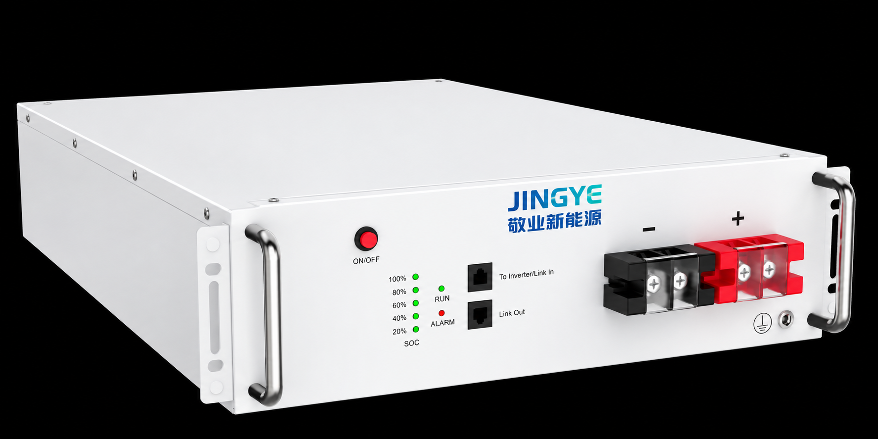
The most effective projects combine a lithium iron phosphate battery, a high-performance power conversion system, a battery management system, an energy management system, and protection equipment. The system must also be sized for the site's power, energy, response time, fault level, and operating conditions.
Voltage is affected by both active power and reactive power. A battery inverter can produce or absorb reactive power without charging or discharging the battery at full power. This allows the system to correct local voltage changes while preserving stored energy.
For example, a 10 MW BESS with a 10 MVA inverter may be able to supply or absorb several megavars of reactive power, depending on the inverter rating and operating point. The exact value depends on the power factor requirement and the connection agreement.
Reactive power control is useful at:
Active power directly affects the balance between supply and demand. When demand rises, the BESS can discharge power. When generation is higher than demand, it can charge.
A four-hour battery rated at 20 MW and 80 MWh can theoretically deliver 20 MW for four hours. In practice, usable energy is lower because operators keep a reserve for safety, battery aging, temperature limits, and emergency services.
Voltage ride-through controls allow the inverter to remain connected during short voltage disturbances. Instead of disconnecting immediately, the system can support the grid and follow the rules set by the network operator.
Project engineers should review:
Grid frequency changes when generation and demand are not equal. In many power systems, the normal target is close to 50 Hz or 60 Hz. A BESS can detect frequency changes and adjust active power output within less than one second.
Fast frequency response helps reduce the size of frequency deviations after a generator trip or sudden load increase. The battery management system monitors state of charge so the battery does not remain at a limit when an emergency response is needed.
A grid-following inverter synchronizes with an existing grid signal. It works well when the network has a stable voltage waveform.
A grid-forming inverter can establish a voltage waveform and support operation in a weak or islanded network. This feature is important for microgrid energy storage, remote power systems, and grids with a high share of inverter-based renewable generation.
| Control mode | Main function | Best use case | Typical design concern |
|---|---|---|---|
| Grid-following | Tracks grid voltage and frequency | Utility-connected solar and wind projects | Needs a stable grid reference |
| Grid-forming | Creates and controls a voltage waveform | Weak grids, islanded systems, and microgrids | Requires advanced controls and protection studies |
| Hybrid control | Switches or coordinates both operating modes | Projects with grid-connected and backup functions | Needs detailed operating logic and testing |
Traditional generators use rotating machines to provide physical inertia. Batteries do not have the same mechanical inertia, but advanced inverters can provide a controlled synthetic response.
This response can begin in tens of milliseconds. It can slow the rate of frequency change and give slower generators more time to respond. The performance depends on inverter firmware, measurement speed, communications, and available battery power.
Peak shaving reduces the highest demand during expensive or congested periods. The BESS discharges during peak load and charges during lower-load periods. This can reduce demand charges and limit stress on transformers and feeders.
The battery absorbs short-term changes in solar or wind output. For example, it can reduce a rapid 5 MW drop caused by cloud movement and release the energy over several minutes.
Energy shifting moves electricity from low-demand periods to high-demand periods. A four-hour system is often used for daily solar shifting, while shorter systems may focus on frequency regulation.
A BESS can remain partly charged and ready to respond when a generator fails or demand rises unexpectedly. The reserve setting must be included in the energy management system schedule.
Some battery systems can energize selected equipment after a blackout. Black start design may require a grid-forming inverter, auxiliary power, communication independence, and coordination with generators and protection systems.
Storage can reduce peak loading on a line or transformer. This may delay a network upgrade when the overload occurs for only a limited number of hours each year.
Correct sizing begins with the service requirement. Engineers should not select a battery only by its energy capacity. Power rating, response time, operating temperature, cycle count, connection voltage, and safety requirements are also important.
| Parameter | Common project range or target | Why it matters |
|---|---|---|
| Power rating | 100 kW to more than 100 MW | Determines how much support the system can provide at one time |
| Energy capacity | 200 kWh to more than 400 MWh | Determines how long the system can deliver power |
| Response time | 10 milliseconds to 1 second | Controls the value for frequency and voltage services |
| Round-trip efficiency | About 85 percent to 95 percent at system level | Affects energy losses and operating cost |
| Operating temperature | Often about -20 C to 50 C with thermal control | Affects power, safety, and battery life |
| Depth of discharge | Often 80 percent to 95 percent, depending on design | Influences usable energy and cycle life |
| Design life | About 10 to 20 years with augmentation planning | Supports financial and maintenance planning |
| Availability target | Often 95 percent to 99 percent | Shows whether the system can meet service commitments |
Lithium iron phosphate batteries are widely used in stationary storage because they offer good thermal stability, long cycle life, and a lower risk of thermal runaway than some other lithium-ion chemistries.
The final selection should also consider cell supplier quality, operating temperature, warranty conditions, degradation rate, system footprint, and recycling requirements.
The power conversion system converts direct current from the battery into alternating current for the grid. It also controls active power, reactive power, voltage, frequency, and protective functions.
Important PCS specifications include:
The battery management system monitors cell voltage, temperature, current, state of charge, and state of health. It can disconnect a battery rack when a safety limit is exceeded.
The energy management system schedules charging and discharging. It also coordinates grid services, weather forecasts, electricity prices, reserve requirements, and site load.
The following process helps project owners select and deploy a battery system for voltage support and grid stability.
Record voltage deviation, frequency events, peak demand, renewable power variation, fault levels, and outage duration. Use data with a time resolution suitable for the service. One-second data may support basic analysis, while millisecond records may be needed for transient studies.
Decide whether the main goal is voltage regulation, frequency regulation, peak shaving, renewable smoothing, backup power, or several services. Each service requires a different power and energy profile.
Calculate the maximum power requirement in MW and the required response duration in minutes or hours. Add reserve energy for temperature limits, degradation, emergency response, and minimum state of charge.
Select the battery chemistry, battery racks, PCS, transformer, switchgear, cooling system, fire protection, control system, and communication network.
Perform load flow, short-circuit, harmonic, transient stability, protection coordination, and electromagnetic transient studies. Review the point of common coupling under normal and fault conditions.
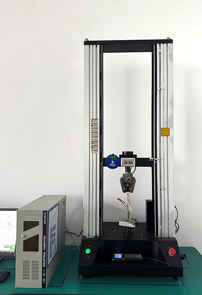
Complete factory acceptance testing, site acceptance testing, protection testing, communication testing, capacity testing, and performance verification.
Monitor cell temperature, state of health, alarms, availability, power quality, and response time. Schedule preventive maintenance and battery augmentation when capacity falls below the project target.
Flow chart:
Grid data collection -> Service definition -> Power and energy sizing -> Equipment selection -> Grid studies -> Factory testing -> Site installation -> Commissioning -> Performance monitoring
Battery energy storage projects should follow the rules that apply in the installation country and utility region. Commonly reviewed standards and codes include IEC 62933 for electrical energy storage systems, IEC 62619 for industrial lithium batteries, IEC 62477-1 for power electronic converter safety, UL 9540 for energy storage systems, UL 9540A for thermal runaway fire propagation testing, NFPA 855 for stationary energy storage installations, and IEEE 1547 for interconnection and interoperability.
Standards do not replace engineering judgment. The project team must also follow local fire codes, electrical codes, utility interconnection rules, and emergency response requirements.
Quality inspections should cover the cell, module, rack, PCS, transformer, container, and control system. Typical checks include:
A project contract should define measurable acceptance criteria. Examples include a response time below 100 milliseconds, a power output accuracy within plus or minus 2 percent, a round-trip efficiency above 85 percent, and system availability above 97 percent. The final values must match the equipment design and service agreement.
Capacity testing should confirm usable energy at the agreed temperature, power level, state-of-charge window, and end-of-test voltage. Testing only at ideal laboratory conditions may not represent field performance.
| Technology | Response speed | Energy duration | Main advantage | Main limitation |
|---|---|---|---|---|
| Battery energy storage | Milliseconds to seconds | Minutes to several hours | Provides active and reactive power with flexible controls | Capacity degrades and requires thermal and fire management |
| Capacitor bank | Cycles to seconds | Short-term reactive support | Low operating cost for fixed reactive power | Limited control flexibility and no energy shifting |
| STATCOM | Milliseconds | Continuous while connected | Fast voltage and reactive power control | Does not provide meaningful energy storage |
| Flywheel | Milliseconds | Seconds to minutes | High cycle capability and fast response | Short duration and mechanical system complexity |
| Diesel generator | Seconds to minutes | Several hours with fuel | Long backup duration | Emissions, noise, fuel cost, and slower response |
A BESS can work with these technologies. For example, a STATCOM may provide continuous reactive power while the battery provides active power and energy shifting.
Consider a 50 MW solar farm connected to a 110 kV transmission network. The site experiences a 12 MW reduction in solar output when clouds pass over the array. The local utility also requires voltage control at the point of common coupling.
A possible solution is a 10 MW and 20 MWh lithium iron phosphate BESS with a 10 MVA power conversion system. The system can reserve part of its capacity for ramp control and part for voltage regulation.
| Metric | Example target |
|---|---|
| Maximum active power response | 10 MW |
| Usable energy | 20 MWh at beginning of life |
| Response time | Less than 100 milliseconds |
| Solar ramp limit | Defined by the utility interconnection agreement |
| Reactive power control | Based on PCS capability and grid code |
| Round-trip efficiency target | At least 88 percent at the agreed test condition |
| Availability target | At least 97 percent |
This design does not remove all grid risks. It must be supported by protection coordination, communications testing, thermal management, and a clear operating schedule.
Jingye can support battery energy storage projects through system planning, equipment integration, quality control, and commissioning coordination. A project team should connect technical design with the actual grid service instead of selecting equipment from a standard catalog.
Important project controls include:
Quantified project experience should be recorded through measurable results. Useful records include the number of commissioned megawatts, installed megawatt-hours, completed factory inspections, tested operating hours, response time results, availability, and capacity retention.
Clarify whether the project needs voltage support, frequency regulation, peak shaving, renewable smoothing, backup power, or black start capability.
Define the maximum MW output, reactive power range, response time, and duration. A system with high MW but low MWh may respond quickly but cannot provide long backup service.
Confirm the required voltage range, frequency range, power factor, fault ride-through, harmonic limits, protection settings, and communication protocol before ordering equipment.
Use written test procedures for power, energy, response time, efficiency, availability, alarms, emergency stop, and communication. The test conditions should include temperature, state of charge, and operating mode.
Ask about cooling maintenance, firmware updates, spare parts, remote monitoring, cell replacement, battery augmentation, fire inspections, and end-of-life recycling.
Battery energy storage for voltage support and grid stability gives grid operators a fast and flexible way to manage changes in power supply and demand. A BESS can supply active power, absorb excess generation, control reactive power, regulate frequency, smooth renewable output, and support backup operation.
The best results come from correct sizing, a suitable power conversion system, reliable battery management, grid-forming or grid-following controls, detailed grid studies, and strict testing. Standards such as IEC 62933, IEC 62619, UL 9540, UL 9540A, NFPA 855, and IEEE 1547 help guide safe and reliable deployment.
With clear performance targets for response time, efficiency, capacity, safety, and availability, Jingye and other qualified project partners can help deliver an energy storage system that improves voltage quality and strengthens long-term grid stability.
Sep. 30, 2026
EV Charging Station Uptime: Common Causes of Downtime
EV charging station uptime is a key factor in the success of every public and commercial charging site. Reliable charging infrastructure helps drivers charge on time and helps operators protect revenue. A station can lose income when a charger is offline, even if the outage lasts only a few hours. DC fast charging sites face added pressure because they use high power, liquid or forced-air
Sep. 29, 2026
Battery Energy Storage for Voltage Support and Grid Stability
Battery energy storage for voltage support and grid stability helps power networks respond to sudden changes in supply and demand.
Sep. 28, 2026
C&I Battery Storage Capacity vs Power Rating: What Is the Difference?
Energy Storage Cabinets are increasingly used by commercial and industrial buyers to reduce peak demand, support critical loads, improve solar self-consumption, and provide backup power. However, many purchasing teams compare systems by price or cabinet size before understanding the two specifications that determine performance: battery storage capacity, measured in kilowatt-hours (kWh), and
Let’s Get Started on Your New Energy Journey.