Oct 13, 2026
Planning an EV charging station requires more than selecting a charger model. You must calculate the EV charging load, check electrical service capacity, and complete utility interconnection before installation. The key conclusion is simple: a site with four 150 kW DC fast chargers may need a 600 kW charging load, but its grid connection often needs 750 kW or more after safety margin, auxiliary equipment, and future growth are included.

EV charging station power requirements depend on the charger type, charger quantity, vehicle battery size, charging speed, local voltage, and how many vehicles charge at the same time. A small workplace station may use less than 100 kW. A highway charging hub with multiple DC fast chargers can require more than 1 MW.
The nameplate power of a charger is the first number to check. A 60 kW DC charger can deliver up to 60 kW to a vehicle under suitable conditions. However, the actual site load can be higher because power is also used by cooling systems, displays, payment systems, lighting, communications, and other equipment.
Use this formula for a first estimate:
Total charger load = Number of chargers x Rated charger power x Simultaneous use factor
For example, six 120 kW chargers with a simultaneous use factor of 0.75 produce an estimated charging load of 540 kW:
6 x 120 kW x 0.75 = 540 kW
The simultaneous use factor reflects real operating behavior. It should not be used to reduce capacity without evidence. A busy highway site may have a factor of 0.90 to 1.00 during peak periods. A workplace site may have a lower factor because vehicles arrive at different times.
Different charging applications require different power levels. AC chargers are often suitable for long parking periods. DC fast chargers are designed for short stops and high vehicle turnover. The table below provides common planning ranges, but local codes and charger specifications must always be checked.
| Charger type | Typical rated power | Typical use | Approximate full-load current at 400 V three-phase |
|---|---|---|---|
| AC Level 2 | 7 to 22 kW | Homes, workplaces, hotels, retail sites | 10 to 32 A |
| DC fast charger | 30 to 180 kW | Public stations, fleets, urban charging | 43 to 260 A |
| High-power DC charger | 240 to 480 kW | Highway hubs, buses, commercial fleets | 346 to 693 A |
Current values are estimates and depend on power factor, efficiency, and operating voltage. A charger rated at 180 kW may draw more than 180 kW from the grid. If the charger has 95 percent efficiency, its input power for a 180 kW output can be about 189.5 kW before other site loads are added.
DC fast charging power demand rises quickly when several vehicles charge at once. Four 180 kW chargers can create a maximum output load of 720 kW. With charger losses and site equipment, the utility may need to support approximately 760 to 800 kW, depending on the design.
Some power-sharing chargers do not deliver their full rated power to every vehicle at the same time. For example, a 480 kW power cabinet may share its output among four charging dispensers. This can reduce the grid connection requirement, but it may also increase charging time when all connectors are occupied.
Grid capacity is the amount of electrical power that the local network and site connection can safely provide. It is not the same as charger output. A complete calculation includes charger input power, existing building demand, auxiliary loads, demand margin, and future expansion.
Required grid capacity = Maximum charger input load + Existing site peak load + Auxiliary load + Design margin
A design margin of 15 to 25 percent is commonly considered during early planning. The final margin depends on local electrical rules, utility requirements, transformer limits, load growth, and the business plan.
| Load item | Example value |
|---|---|
| Four 150 kW DC chargers | 600 kW output load |
| Estimated charger input at 95 percent efficiency | About 632 kW |
| Lighting, networking, cooling, and payment systems | 18 kW |
| Existing building peak load | 80 kW |
| Subtotal | About 730 kW |
| 15 percent planning margin | About 110 kW |
| Recommended initial grid capacity | About 840 kW |
This example shows why a 600 kW charger label does not mean that a 600 kW utility connection is sufficient. A practical design may require an 800 kW or 1 MW connection, depending on the utility's available service ratings.
Understanding electrical units prevents common design mistakes. kW describes power at a given moment. kWh describes energy used over time. kVA describes apparent power used for transformer and electrical equipment sizing. Amps describe current in the conductors.
| Unit | Meaning | Why it matters for charging stations |
|---|---|---|
| kW | Instant power | Used to describe charger output and peak site load |
| kWh | Energy used over time | Used for electricity billing and daily energy planning |
| kVA | Apparent electrical power | Used for transformer, switchgear, and service sizing |
| Amps | Electrical current | Used to size cables, breakers, and protection equipment |
For a three-phase system, a basic current estimate is:
Current = Power in watts / (1.732 x Voltage x Power factor)
At 400 V, three-phase power, and a power factor of 0.98, a 500 kW load requires approximately 737 amps. This is a major electrical load. It may require medium-voltage service, larger switchgear, parallel cables, or a dedicated transformer.
Many commercial sites have spare electrical capacity, but the available capacity must be verified. The utility bill alone is not enough. A site may have a 1,000 kVA transformer, yet the building already uses 700 kVA during its peak period. The remaining capacity may not support several DC fast chargers.
A load study is strongly recommended for sites above 150 kW. It can identify peak demand, voltage drop, power quality, harmonic distortion, and equipment temperature. These results help prevent charger shutdowns and expensive redesign work.
The following process gives overseas buyers and distributors a clear project path.
Planning flow: Traffic demand - Charger selection - Load calculation - Site survey - Utility review - Electrical design - Installation - Commissioning - Load monitoring
A weak grid connection does not always stop an EV charging project. Several solutions can reduce the required connection or improve operating performance. The best choice depends on charging demand, land conditions, utility rules, and the cost of downtime.
| Solution | How it works | Best application | Main limitation |
|---|---|---|---|
| Dynamic load management | Shares available power among chargers | Sites with changing demand | Some vehicles may charge more slowly |
| Battery energy storage | Charges during low demand and supports peak charging | High-power sites with limited grid service | Higher capital and maintenance cost |
| Solar plus storage | Uses solar energy and battery discharge | Sites with suitable roof or land area | Solar output changes with weather and time |
| Phased expansion | Installs chargers in planned stages | New stations with uncertain demand | Future construction may be required |
| Medium-voltage connection | Provides a larger utility service | Large highway and fleet hubs | Longer approval and construction process |
Power management can reduce the difference between theoretical maximum load and real operating load. A controller may limit total station demand to 400 kW while assigning available power to vehicles based on battery status, departure time, or service priority.
However, power management should not be used as a hidden substitute for proper grid planning. The system must be tested at its maximum programmed limit, and the utility must accept the control method where required.
Transformer sizing should consider both kW and kVA. A transformer that is too small may overheat, cause voltage drop, or limit charger performance. A transformer that is much larger than needed can increase installation cost and reduce project efficiency.
For early planning, many designers select transformer capacity above the calculated maximum demand. For example, a site with an expected 730 kW demand may review a 1,000 kVA transformer, subject to power factor, local code, ambient temperature, ventilation, and future expansion.
Other equipment may include medium-voltage switchgear, low-voltage distribution panels, circuit breakers, surge protection, grounding systems, emergency stops, communication networks, and metering. The cable length between the transformer and charger also affects voltage drop and installation cost.
Grid capacity can strongly affect the total cost of an EV charging station. The charger is only one part of the project. Civil works, utility studies, transformer upgrades, switchgear, trenching, cables, permits, and installation labor may equal or exceed the equipment price.
| Project condition | Likely electrical scope | Planning effect |
|---|---|---|
| Existing low-voltage spare capacity | New breakers, cables, and local distribution | Shorter schedule and lower infrastructure cost |
| Limited transformer capacity | Transformer or switchboard upgrade | Additional engineering and utility coordination |
| Large DC fast charging hub | Medium-voltage service and dedicated transformer | Higher civil cost and longer approval time |
| Remote location with weak grid | Storage, solar, or utility network extension | More complex design and operating controls |
Overseas buyers should ask for a complete technical offer rather than comparing charger prices alone. A useful offer should state input voltage, maximum input current, efficiency, power factor, protection rating, communication protocol, operating temperature, cable length, and power-sharing capability.
A 150 kW charger may need about 158 to 165 kW of input power after efficiency losses. The site should also include auxiliary loads, existing building demand, and a design margin. The final service requirement may be close to 200 kW or higher.
They may operate with controlled power sharing. Their maximum output is 480 kW, leaving little room for losses and other site loads on a 500 kW connection. A higher connection or a strict load management system is safer.
Not always. A small charger may connect to an existing low-voltage distribution system if capacity and protection are suitable. Larger stations often require a dedicated transformer or medium-voltage connection.
Provide charger quantity, rated output, input voltage, maximum input current, power factor, efficiency, operating schedule, existing site peak demand, one-line electrical diagram, and future expansion plans.
Jingye can support charger selection by matching DC fast charging power, connector requirements, communication functions, cabinet architecture, and power management needs to the project. Buyers should provide the local voltage, site type, target charging time, charger quantity, and available utility capacity for a more accurate proposal.
The correct EV charging station power requirements come from a complete load calculation, not from the charger nameplate alone. Start with vehicle demand, calculate simultaneous charging, add input losses and existing loads, then confirm transformer and utility capacity.
For many projects, the best design is not the highest charger rating. It is the design that delivers the required charging time while keeping the grid connection, electrical equipment, installation schedule, and future expansion under control. With accurate data and early utility coordination, Jingye and its overseas partners can build charging stations that are safe, scalable, and ready for commercial operation.
Oct. 20, 2026
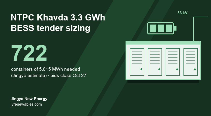
NTPC Khavda 3,300 MWh BESS Tender: How Many Containers You Really Need (2026)
NTPC Green Energy's 1,100 MW / 3,300 MWh Khavda battery tender closes on October 27, 2026. Because capacity is counted as AC energy at the grid point, we estimate it needs about 722 containers of 5.015 MWh, roughly 10% more installed battery than the headline figure.
Oct. 20, 2026
Battery Energy Storage System Architecture: Key Components Explained
A battery energy storage system architecture determines how safely and efficiently a BESS stores, controls, and delivers electricity. The main challenge for overseas buyers is choosing the right structure without creating avoidable cost, safety, or integration problems.
Oct. 19, 2026
Battery Capacity Fade in Commercial Energy Storage Systems
Battery capacity fade in commercial energy storage systems reduces the amount of energy a site can store and deliver. This battery degradation can increase demand charges, reduce backup time, and change the return on investment.
Let’s Get Started on Your New Energy Journey.