Sep 23, 2026
Selecting the wrong Energy Storage Cabinet Voltage: Why It Matters for System Design is not a minor specification error—it can undermine the safety, efficiency, scalability, and financial performance of an entire battery energy storage system (BESS). A cabinet designed for a nominal 768 VDC battery architecture cannot simply be connected to a power conversion system (PCS) configured for a 1,000 VDC operating window without checking voltage compatibility, insulation coordination, current limits, state-of-charge behavior, and protection settings. If this issue is neglected, the result may include nuisance trips, accelerated battery degradation, DC arcing, inverter derating, failed commissioning tests, or an expensive redesign after equipment has already arrived on-site. At Jingye, we treat cabinet voltage as a system-level design parameter—not merely a label on a battery datasheet.
!
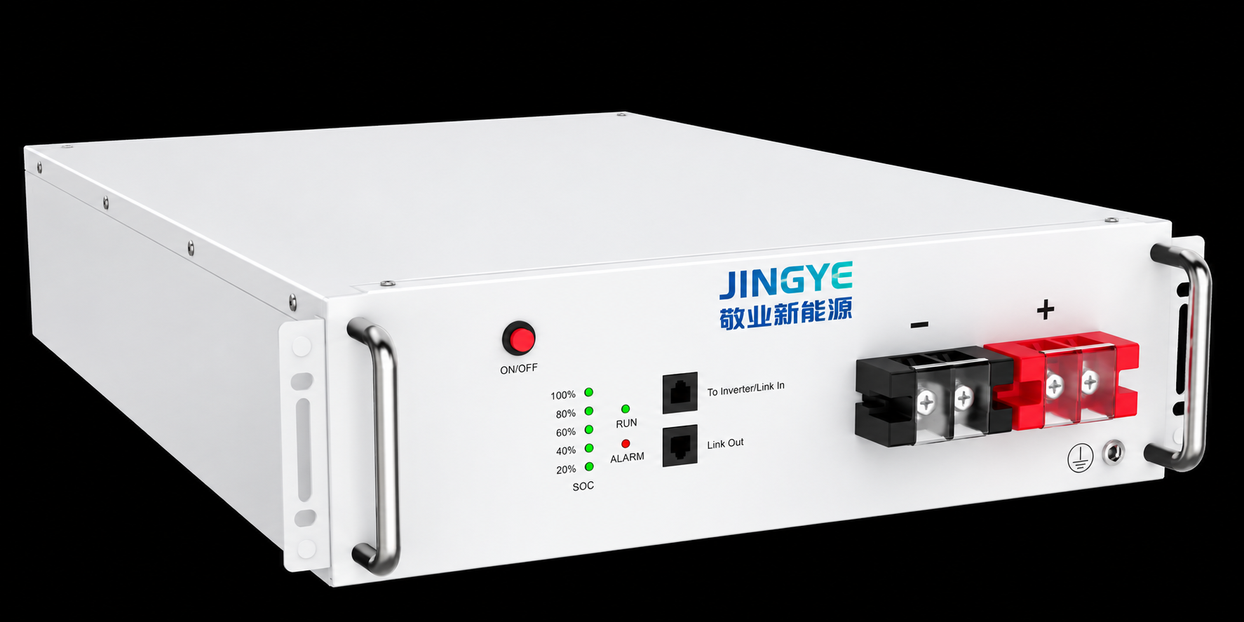
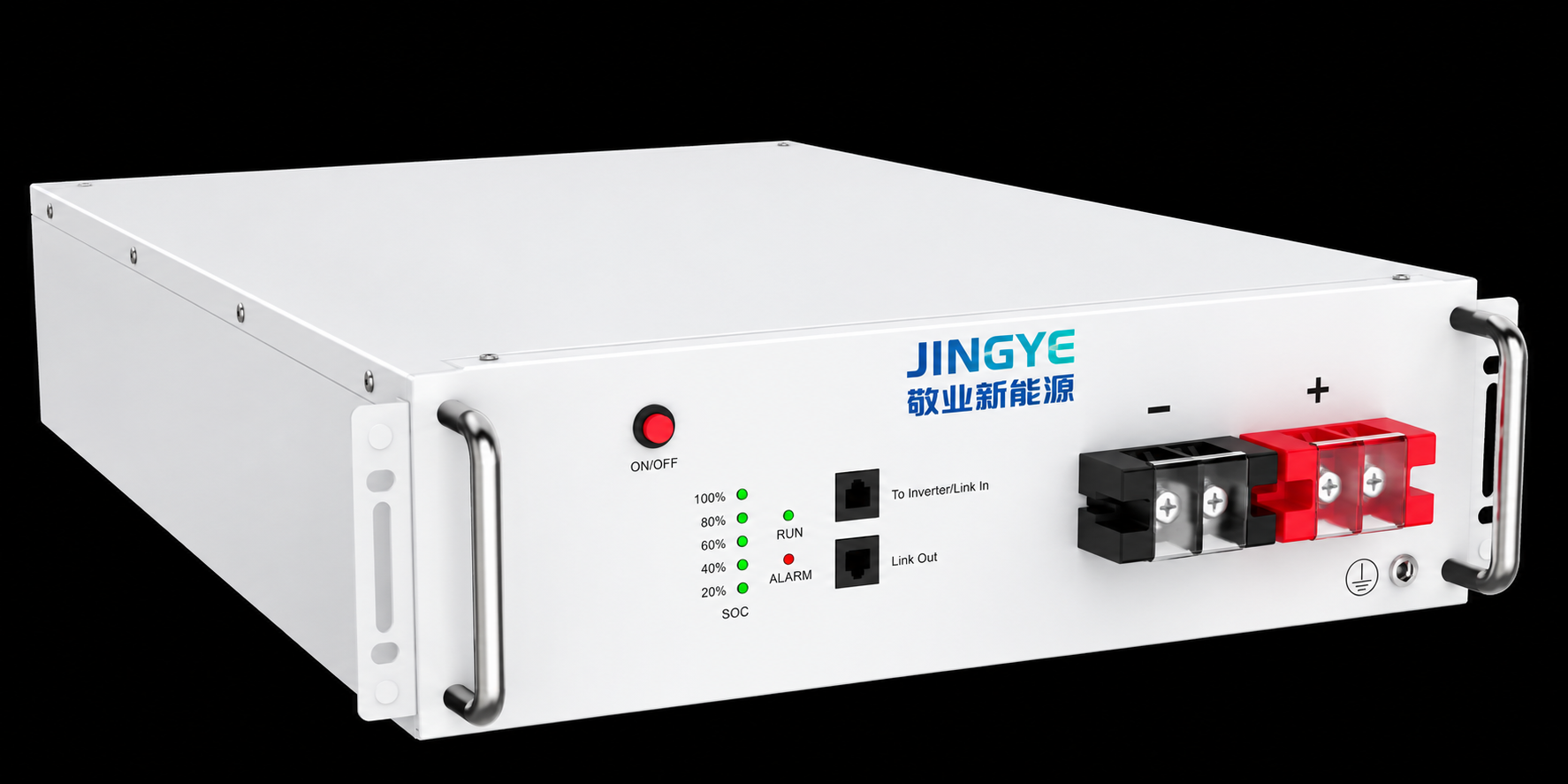
Energy Storage Cabinets combine battery cells, modules, a battery management system (BMS), contactors, fuses, thermal management equipment, and communication interfaces into a controlled DC power unit. The cabinet voltage determines how these components interact with the PCS, transformer, DC combiner, cable system, and energy management system (EMS).
The most important values are not the nominal voltage alone. Engineers must evaluate:
For example, a lithium iron phosphate (LFP) battery module commonly uses cells with a nominal voltage around 3.2 V. A 240-series configuration has a nominal voltage of approximately:
240 × 3.2 V = 768 VDC
However, the fully charged voltage may be substantially higher, depending on the cell’s upper voltage limit and the BMS control strategy. Therefore, a “768 V cabinet” may operate across a wider range, such as approximately 600–876 VDC, depending on the selected cell chemistry, series count, SOC limits, temperature, and protection settings. The final voltage window must always be confirmed in the approved electrical design and manufacturer datasheet.
Battery cells connected in series increase voltage. Cells connected in parallel increase capacity and current capability. This creates a direct design relationship between voltage, power, and current:
Power (kW) = Voltage (V) × Current (A) ÷ 1,000
For a 1 MW DC battery system:
This simplified comparison shows why higher-voltage Energy Storage Cabinets can reduce conductor current for the same power level. Lower current may allow smaller cable cross-sections, reduced copper usage, lower I²R losses, and more manageable busbar dimensions.
The trade-off is that higher voltage increases insulation, creepage, clearance, switching, and arc-flash requirements. A high-voltage battery cabinet therefore requires more than additional battery modules. It needs suitable contactors, pre-charge circuits, DC fuses, insulation monitoring, service disconnects, and arc-resistant design measures.
Battery voltage is dynamic. It changes with:
A cabinet may have a nominal voltage of 768 VDC but deliver a much lower voltage at low SOC and high discharge current. Conversely, voltage can rise near the upper SOC limit during charging. If the PCS operates outside its specified DC input range, it may shut down or limit power precisely when grid support is required.
This is why system designers should compare the complete battery voltage curve with the PCS operating envelope rather than matching only the nominal voltage.
A voltage mismatch can occur in several ways:
These issues can remain hidden during factory testing if the battery is tested at moderate SOC and room temperature. They often appear during site acceptance testing (SAT), cold-weather operation, high-power discharge, or emergency backup conditions.
Voltage selection directly influences the bill of materials, installation labor, operating efficiency, and long-term service requirements.
When current is reduced, resistive loss generally decreases according to the relationship:
P loss = I²R
If current is reduced by half while cable resistance remains unchanged, theoretical resistive loss falls to one-quarter. In practice, the final efficiency depends on cable length, conductor size, busbar design, PCS efficiency, contact resistance, and thermal conditions.
For commercial and industrial projects, the business impact may include:
However, purchasing a higher-voltage cabinet solely to reduce current can be counterproductive if the project lacks qualified high-voltage maintenance personnel or if the PCS and protection equipment are not designed for that architecture.
The DC voltage level affects the risk assessment and compliance pathway. Project teams may need to consider:
The applicable standard depends on the project location, equipment category, voltage class, and authority having jurisdiction. Compliance cannot be established by quoting a single standard in isolation. A qualified engineer should confirm the complete certification and permitting route.
We recommend the following engineering sequence before approving an Energy Storage Cabinet specification.
Start with the application:
A two-hour peak-shaving system may use a different battery architecture from a high-power frequency-regulation system, even if both have the same nominal energy capacity.
Do not specify only “800 V battery.” Request a complete table showing:
| Parameter | Required design information |
|---|---|
| Nominal voltage | Reference battery voltage |
| Maximum voltage | Full-charge and high-temperature limit |
| Minimum voltage | Low-SOC and high-load limit |
| Recommended operating range | Normal BMS-controlled window |
| Absolute voltage limit | Protection boundary |
| Maximum continuous current | Charge and discharge |
| Peak current | Duration and duty cycle |
| Insulation resistance | Test method and acceptance value |
| Voltage measurement accuracy | BMS and service measurement |
| DC withstand level | Applicable test requirement |
At Jingye, this voltage map should be reviewed against the PCS datasheet, cable schedule, protection coordination study, and EMS control logic before production release.
The PCS must support the battery cabinet’s entire practical operating range. Key checks include:
The transformer is generally connected on the AC side, but its rating still affects the usable output of the BESS. A 1 MW battery cabinet system connected to an undersized transformer may be forced to derate, causing the project to miss its contracted power capacity.
For long cable routes, voltage drop can cause a difference between the cabinet terminal voltage and PCS terminal voltage. Engineers should calculate:
Cable ampacity should be verified using the applicable regional standard and installation conditions. A cable that appears adequate at 25°C may require derating inside a hot cabinet, cable trench, or container.
Voltage affects the selection and settings of:
Protection settings should be coordinated so that a fault is cleared selectively without unnecessarily disconnecting healthy cabinets. The BMS, PCS, fire alarm system, and EMS must also share a clearly defined emergency shutdown sequence.
Consider a commercial BESS designed for a 1 MW discharge rating. The project team initially selects a cabinet with a nominal voltage of 768 VDC and assumes the PCS will deliver full power across the entire SOC range.
During detailed engineering, the team identifies the following:
The cabinet and PCS are technically connectable, but they are not fully power-compatible. At low SOC, the PCS cannot provide the contracted 1 MW without exceeding its current limit. The design team resolves the issue by:
This is an illustrative engineering scenario, not a universal performance guarantee. Its lesson is practical: nominal voltage compatibility does not prove full-load compatibility.
A structured review performed before purchase is normally far less expensive than replacing a PCS, modifying a DC bus, or accepting permanent power derating after installation.
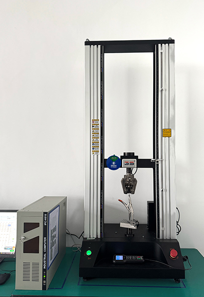
Voltage performance must be verified through documented inspection and testing. A robust quality plan may include:
Testing parameters must follow the approved product design and applicable standards. For lithium battery systems, IEC 62619, IEC 62477-1, UL 9540, UL 9540A, and local regulations may be relevant depending on the market.
Quality documentation should include serial-number traceability, calibration records, test results, inspection photographs, and nonconformance reports. Jingye can also align inspection checkpoints with customer requirements, such as 100% inspection of critical electrical connections and a 24-hour technical response target for urgent commissioning support, subject to the project service agreement.
Ignoring voltage coordination creates technical, commercial, and operational risks.
The risk becomes more serious when business conditions change. A facility may later add solar photovoltaic generation, increase peak demand, participate in frequency regulation, or operate more frequently during utility outages. A voltage architecture that was acceptable for light cycling may become unsuitable for high-power dispatch or expanded cabinet capacity.
A battery system operating outside its validated voltage range may experience abnormal heating, insulation breakdown, contactor failure, or protection delays. In severe cases, electrical faults can contribute to arcing or thermal events. Voltage design must therefore be integrated with thermal runaway mitigation, fire detection, ventilation, separation distances, and emergency response procedures.
Before energization, we recommend confirming the following:
Energy Storage Cabinet Voltage: Why It Matters for System Design is ultimately a question of compatibility, safety, efficiency, and lifecycle value. The correct voltage architecture reduces current-related losses and supports reliable PCS operation, while the wrong architecture can create derating, commissioning delays, warranty exposure, and serious safety risks.
Jingye helps project teams evaluate the complete DC voltage window, battery configuration, PCS interface, protection system, thermal conditions, and applicable standards before equipment production. Whether the project requires commercial peak shaving, renewable energy integration, microgrid backup, or utility-scale energy storage, we recommend treating voltage coordination as an early design gate.
Before selecting your next Energy Storage Cabinets solution, request a complete voltage map, verify the PCS operating envelope, review applicable IEC or UL requirements, and complete a documented protection coordination study. A careful voltage decision today can protect system performance and business value for years.
Sep. 23, 2026
Energy Storage Cabinet Voltage: Why It Matters for System Design
Selecting the wrong Energy Storage Cabinet Voltage: Why It Matters for System Design is not a minor specification error—it can undermine the safety, efficiency, scalability, and financial performance of an entire battery energy storage system (BESS). A cabinet designed for a nominal 768 VDC battery architecture cannot simply be connected to a power conversion system (PCS) configured for a 1,000
Sep. 23, 2026
Energy Storage Cabinet Thermal Management and Battery Performance
Energy storage cabinet thermal management directly affects battery performance, safety, service life, and operating cost. A battery energy storage system produces heat during charging and discharging, even when it operates within its rated power range. Poor heat dissipation can increase internal resistance and reduce usable capacity.
Sep. 22, 2026
Why EV Charger Efficiency Matters for Commercial Charging Operations
A commercial charging site can lose thousands of dollars each year through inefficiency long before an operator notices a hardware failure. When a DC fast EV charger converts grid electricity into battery power, energy is lost as heat, switching loss, cable loss, cooling demand, and standby consumption. A charger operating at 94% efficiency instead of 97% may appear to differ by only three
Let’s Get Started on Your New Energy Journey.